Vehicle photovoltaic unfolding device and working method

A technology for photovoltaics and vehicles, applied in the field of photovoltaic deployment devices for vehicles, which can solve the problems of conventional use, large volume of photovoltaic modules, unfavorable handling of photovoltaic modules, etc., and achieve the effect of large power supply

Pending Publication Date: 2021-01-01
英利能源(江西)有限公司
View PDF0 Cites 3 Cited by
  • Summary
  • Abstract
  • Description
  • Claims
  • Application Information

AI Technical Summary

Problems solved by technology

[0004] 1. Conventional photovoltaic modules are large in size, for example, a photovoltaic module of about 300W has an area of ​​1.9 square meters (about 1m x 1.9m);
[0005] 2. The usable environment of the car is poor. The top of the car usually has a radian, and there is no completely flush installation environment, and the usable installation area on the top is small. For example, the usable area on the top of a common SUV is only 0.9x1.2 meters. Only one photovoltaic module of about 100W can be installed, and one photovoltaic module is far from enough for common electrical appliances in the car. For example, the power of a notebook is about 120 watts, which cannot be used by the people in the car;
[0006] 3. It is inconvenient to carry. Large-area photovoltaic modules are not conducive to transportation. For example, large-area photovoltaic modules cannot be put into the trunk of a car at all, and there is no way to fix them on the roof rack;
[0007] 4. Conventional photovoltaic modules are difficult to install and disassemble. Usually, after being installed in a certain environment, they are basically not disassembled. In the automotive environment, various automotive accessories are usually required to be easy to install and remove to cope with various environmental conditions;

Method used


Image

  • Vehicle photovoltaic unfolding device and working method
  • Vehicle photovoltaic unfolding device and working method
  • Vehicle photovoltaic unfolding device and working method

Examples


Embodiment Construction

[0030] In order to make the above-mentioned features and advantages of the present invention more comprehensible, the following specific embodiments are described in detail with reference to the accompanying drawings.

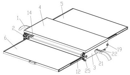
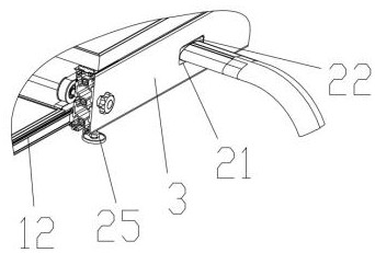
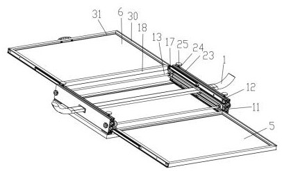
[0031] The vehicle photovoltaic deployment device of the present invention includes a mounting beam 1 arranged on the roof of the vehicle and a left mounting frame 2 and a right mounting frame 3 oppositely arranged on the mounting beam. The mounting beam 1 may have a circular or elliptical cross-section, etc. The aluminum pipe is bent and formed, and the two ends of the installation beam 1 are connected to the roof through the support base. The support base can be a pipe sleeve with a flange. The screws are locked on the roof; the first photovoltaic panel 4, the second photovoltaic panel 5 and the third photovoltaic panel 6 are arranged from top to bottom between the left and right installation frames, and the first photovoltaic panel 4 is fixed on the left and ...


PUM


Abstract

The invention relates to a vehicle photovoltaic unfolding device and a working method thereof. The vehicle photovoltaic unfolding device comprises an installation crossbeam arranged on a vehicle roof,and a left installation frame and a right installation frame which are oppositely arranged on the installation crossbeam, and a first photovoltaic panel, a second photovoltaic panel and a third photovoltaic panel are arranged between the left installation frame and the right installation frame from top to bottom. The first photovoltaic panel is fixed between the left installation frame and the right installation frame, the second photovoltaic panel and the third photovoltaic panel slide relative to the left installation frame and the right installation frame in the length direction of the vehicle body, and the second photovoltaic panel and the third photovoltaic panel achieve synchronous stretching and retracting through a belt wheel synchronizing mechanism arranged on the inner side of the left installation frame and the inner side of the right installation frame. The photovoltaic unfolding device for the vehicle can be used on the vehicle, large power supply power can be provided after the photovoltaic unfolding device is unfolded, and the photovoltaic unfolding device is stable and reliable in installation.

Description

Technical field: [0001] The invention relates to a vehicle-used photovoltaic deployment device and a working method thereof. Background technique: [0002] After decades of development, photovoltaic technology has become more and more widely used, and has been applied to various installation environments. However, due to the large size, heavy weight, and low power of photovoltaic modules, the installation area of ​​automobiles is limited, and automotive appliances have high power requirements, etc. The reason is that photovoltaic modules have not been well applied to automobiles. [0003] Conventional photovoltaic module structures are monolithic. Cells are packaged with glass plates, backplanes and EVA. The cells are connected in series. After that, EVA is laid on both sides of the cells and placed between the battery strings and the backplane. Laminator, heating to melt EVA, bonding the layers together, and finally cooling and taking out the photovoltaic module. If the co...

Claims


Application Information

Patent Timeline
Patent Type & Authority Applications(China)
IPC IPC(8): H02J7/35H02S30/10H02S30/20H02S20/30H02S10/40
CPCH02J7/35H02S10/40H02S20/30H02S30/10H02S30/20Y02E10/56
Inventor 陈俊超张作仁赵春涛
Owner 英利能源(江西)有限公司
Why Eureka
Try Eureka