
Numerical control lathe push-pull type protective cover structure capable of preventing falling

A technology of CNC lathe and protective cover, which is applied in the field of protective cover, can solve the problems of inconvenient use and large size of protective cover, and achieve the effect of increasing the service life

Inactive Publication Date: 2021-01-05
ANHUI AOYU CNC TECH
View PDF6 Cites 2 Cited by
  • Summary
  • Abstract
  • Description
  • Claims
  • Application Information

AI Technical Summary

Problems solved by technology

It is used to protect the machine tool. He can protect the surface of the machine tool from external corrosion and damage, useful steel wire support type and suture type. There are also rolling shutter protective covers and armor protective covers. The previous protective covers were too large and inconvenient to use. Therefore, we propose a push-pull protective cover structure for CNC lathes to prevent falling off to solve the above problems.

Method used

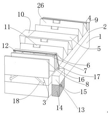
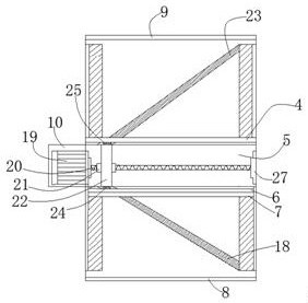

Image

  • Numerical control lathe push-pull type protective cover structure capable of preventing falling
  • Numerical control lathe push-pull type protective cover structure capable of preventing falling
  • Numerical control lathe push-pull type protective cover structure capable of preventing falling

Examples


Embodiment Construction

[0016] The following will clearly and completely describe the technical solutions in the embodiments of the present invention with reference to the accompanying drawings in the embodiments of the present invention. Obviously, the described embodiments are only some, not all, embodiments of the present invention. Based on the embodiments of the present invention, all other embodiments obtained by persons of ordinary skill in the art without making creative efforts belong to the protection scope of the present invention.

[0017] see Figure 1-3 , the present invention provides a technical solution: a push-pull protective cover structure for a CNC lathe to prevent falling off, including a body 1 and a protective cover 26, two parallel fixed blocks 2 are fixedly installed on the body 1, and two ends of the body 1 are fixed Electromagnetic plate three 8 and electromagnetic plate four 9 are provided, and a foldable protective cover 26 is installed on the fixed block 2, and the midd...


PUM


Abstract

The invention discloses a numerical control lathe push-pull type protective cover structure capable of preventing falling. The numerical control lathe push-pull type protective cover structure is characterized in that two parallel fixing blocks are fixedly installed on a machine body, a protective cover is installed on the fixing blocks, a collecting device is arranged in the middle of the protective cover, a motor is installed in a first motor box installed beside the collecting device, and the driving end of the motor is fixedly connected with a rotating shaft; and a sleeve rod is movably connected to the rotating shaft in a sleeving manner, a telescopic rod is fixedly connected on the sleeve rod, a thread device is fixedly arranged on the rotating shaft, the thread device and threads inthe sleeve rod are mutually clamped, and a roller I and a roller II are fixedly arranged at the two ends of the telescopic rod. When a machine works normally, the motor drives the telescopic rod installed on the sleeve rod on the rotating shaft to move forwards, due to the fact that the two ends of the telescopic rod are fixedly installed on a hollow plate and a first electromagnetic plate at thetwo ends of the protective cover respectively, the telescopic rod moves forwards to drive the protective cover to move forwards, the telescopic rod moves forwards when the motor rotates forwards, thetelescopic rod moves backwards when the motor rotates reversely, and the push-pull effect of the protective cover is achieved.

Description

technical field [0001] The invention relates to the technical field of protective covers, in particular to a push-pull protective cover structure for a numerically controlled lathe that prevents falling off. Background technique [0002] The protective cover can strictly prevent dust, chips, hard sand, etc. from entering the track, reduce the damage of hard granular foreign matter to the sliding rail surface, reduce the influence of the guide rail on the machining accuracy due to operation deformation, and maintain the machining accuracy of the machine tool. The surface of the protective cover should be smooth without burrs and sharp edges and corners, and should not become a new source of danger; and the protective cover should not affect the line of sight and normal operation, and should be convenient for equipment inspection and maintenance; the machine tool protective cover is used to protect the steel plate and stainless steel of the machine tool. The protective cover h...

Claims


Application Information

Patent Timeline
Patent Type & Authority Applications(China)
IPC IPC(8): B23Q11/08B23Q11/12B23Q11/00
CPCB23Q11/0816B23Q11/126B23Q11/005
Inventor 徐昆
Owner ANHUI AOYU CNC TECH
Learn More