Multi-size shock absorber assembly fixture

A technology for assembling fixtures and shock absorbers, which is applied in the direction of manufacturing tools, hand-held tools, workpiece clamping devices, etc., can solve problems such as insufficient clamping of shock absorbers, lower production efficiency, and affect product use, etc., to achieve effective Conducive to recycling, saving resources and materials, and improving the service life

Active Publication Date: 2021-01-05
深圳市鸿邦达机械工具有限公司
View PDF6 Cites 1 Cited by
  • Summary
  • Abstract
  • Description
  • Claims
  • Application Information

AI Technical Summary

Problems solved by technology

[0002] The shock absorber is used to suppress the shock when the spring rebounds after absorbing the shock and the impact from the road. The production process of the shock absorber is complicated, including the assembly of the shock absorber. During this process, the shock absorber needs to be fixed, but now When some assembly jigs clamp the shock absorber, they will be subjected to a strong force from the air gun, causing the shock absorber to shake and shift, increasing the difficulty of the work
[0003] During the use of the existing assembly fixture, the clamping of the shock absorber is not stable enough. When impacted by the air gun, the shock absorber will be displaced, resulting in eccentricity and edge deviation of the assembled parts, which will affect the use of the product. It causes waste of resources and materials, reduces the pass rate of products, and at the same time, the existing assembly method cannot clamp shock absorbers of different sizes, which has large limitations and poor applicability. It is not suitable for large-scale production and will reduce Productivity

Method used


Image

  • Multi-size shock absorber assembly fixture
  • Multi-size shock absorber assembly fixture
  • Multi-size shock absorber assembly fixture

Examples


Embodiment Construction

[0024] The following will clearly and completely describe the technical solutions in the embodiments of the present invention with reference to the accompanying drawings in the embodiments of the present invention. Obviously, the described embodiments are only some, not all, embodiments of the present invention. Based on the embodiments of the present invention, all other embodiments obtained by persons of ordinary skill in the art without making creative efforts belong to the protection scope of the present invention.

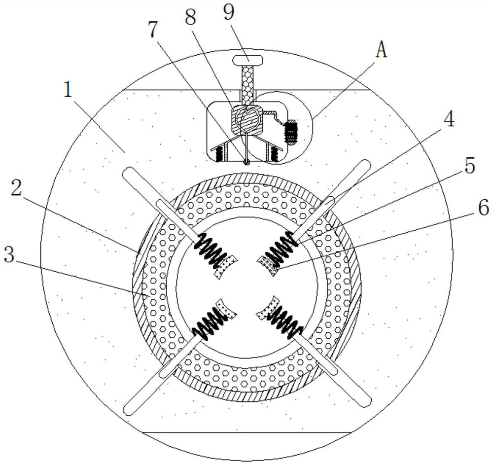
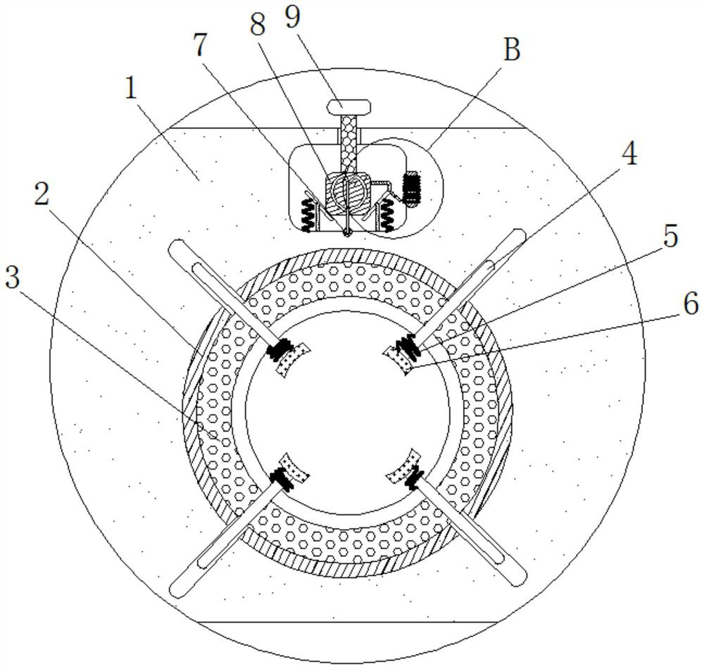
[0025] see Figure 1-4 , a multi-size shock absorber assembly fixture, including a housing 1, the inner wall of the housing 1 is fixedly connected with a conductive ring 2, and the inner wall of the housing 1 is provided with a current variant slot 3 near the inner side of the conductive ring 2, and the current The inside of the variant tank 3 is filled with electrovariant, the main components of the electrovariant are gypsum, lime, carbon powder and olive oil...


PUM


Abstract

The invention relates to the technical field of shock absorbers, and discloses a multi-size shock absorber assembly fixture. The multi-size shock absorber assembly fixture comprises a shell, wherein aconducting ring is fixedly connected to the inner wall of the shell, an electrorheological fluid groove is formed in the inner wall of the shell and is close to the inner side of the conducting ring,a push rod is connected to the inner wall of the shell in a sliding mode, a reset spring is fixedly connected to the inner side of the shell and is close to the outer side of the push rod, a clampingblock is fixedly connected to the inner side of the push rod, and a connecting disc is fixedly connected to the inner wall of the shell. According to the multi-size shock absorber assembly fixture, the resistance value of a slide rheostat is changed by pushing a pressing rod, so that in the using process of the assembly fixture, the clamping stability of a shock absorption cylinder can be increased, the shock absorption cylinder is prevented from displacing when being impacted by an air gun, assembled parts are prevented from being eccentric and deviated, the use of products is optimized, resources and materials are saved, the qualified rate of the products is increased, the multi-size shock absorber assembly fixture is suitable for large-scale production, and the production efficiency can be improved.

Description

technical field [0001] The invention relates to the technical field of shock absorbers, in particular to a jig for assembling multi-size shock absorbers. Background technique [0002] The shock absorber is used to suppress the shock when the spring rebounds after absorbing the shock and the impact from the road. The production process of the shock absorber is complicated, including the assembly of the shock absorber. During this process, the shock absorber needs to be fixed, but now When some assembly jigs clamp the shock absorber, they will be subjected to a strong force from the air gun, causing the shock absorber to shake and shift, increasing the difficulty of the work. [0003] During the use of the existing assembly fixture, the clamping of the shock absorber is not stable enough. When impacted by the air gun, the shock absorber will be displaced, resulting in eccentricity and edge deviation of the assembled parts, which will affect the use of the product. It causes w...

Claims


Application Information

Patent Timeline
IPC IPC(8): B25B11/02B25B27/00
CPCB25B11/02B25B27/00
Inventor 王哲涵
Owner 深圳市鸿邦达机械工具有限公司
Why Eureka
Try Eureka