
Intelligent clamping device for mechanical part machining

A technology of mechanical parts and clamping devices, which is applied in the field of mechanical processing, can solve problems such as insufficient intelligence, low work efficiency, and time-wasting clamping positions, and achieve the effects of intelligence in the use process, improved work efficiency, and convenient processing operations

Inactive Publication Date: 2021-01-05
邱海姑
View PDF0 Cites 0 Cited by
  • Summary
  • Abstract
  • Description
  • Claims
  • Application Information

AI Technical Summary

Problems solved by technology

[0003] However, the clamping devices currently on the market are manually operated or electrically controlled by buttons. The use of the device is not intelligent enough, the work efficiency is low, and it is inconvenient to use. Generally, the clamping device with electric control clamping does not have The safety protection function is easy to cause danger to the user. Most of the clamping structures generally have to be placed on the table for clamping, which is not conducive to processing the lower end of the material. It is time-consuming to adjust the clamping position again when processing is required. The clamping surface of the general device There is no anti-slip structure, which is not conducive to protecting the outer surface of the material during clamping, causing wear and tear on the clamping place of the material, and most of them cannot easily adjust the height of the clamping position, and most of them cannot adapt to clamping objects of different sizes, which is not conducive to increasing the use range of the device

Method used


Image

  • Intelligent clamping device for mechanical part machining
  • Intelligent clamping device for mechanical part machining
  • Intelligent clamping device for mechanical part machining

Examples


Embodiment Construction

[0020] The following will clearly and completely describe the technical solutions in the embodiments of the present invention with reference to the accompanying drawings in the embodiments of the present invention. Obviously, the described embodiments are only some, not all, embodiments of the present invention. Based on the embodiments of the present invention, all other embodiments obtained by persons of ordinary skill in the art without making creative efforts belong to the protection scope of the present invention.

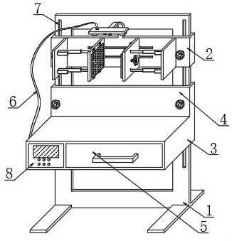
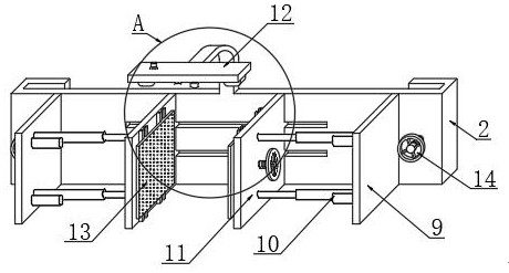
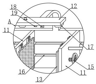
[0021] see Figure 1~5 , in an embodiment of the present invention, an intelligent clamping device for processing mechanical parts, including a bracket 1, the upper end of the bracket 1 is slidably installed with a clamping seat 2, and the upper end of the bracket 1 is slidably installed at a position below the clamping seat 2 Adjusting plate 4 is arranged, and the lower end of adjusting plate 4 is welded with table top 3, drawer 5 is installed on one side of ...


PUM


Abstract

The invention relates to the technical field of machining, and specifically relates to an intelligent clamping device for mechanical part machining. The intelligent clamping device for mechanical partmachining comprises a support, wherein a clamping seat is slidably installed at the upper end of the support; an adjusting plate is slidably installed at the upper end of the support and located below the clamping seat; a table top is welded to the lower end of the adjusting plate; a drawer is installed at one side of the front surface of the table top; a control box is installed at the other side of the front surface of the support; a detection component is installed on the upper surface of the clamping seat; a conductive wire is installed at the output end of the detection component; and aheight adjusting sliding groove is formed in one side of the front surface of the support. The intelligent clamping device for mechanical part machining is provided with the detection component, materials are automatically clamped, whether the operation of a user is dangerous or not is analyzed through infrared induction video analysis processing, the relative distance between the clamping seat and the table top can be adjusted, and a replaceable anti-skid structure is arranged on the clamping surface of the device.

Description

technical field [0001] The invention relates to the technical field of mechanical processing, in particular to an intelligent clamping device for processing mechanical parts. Background technique [0002] The production process of a machine refers to the entire process of making a product from raw materials (or semi-finished products). For machine production, it includes transportation and storage of raw materials, preparation for production, manufacturing of blanks, processing and heat treatment of parts, assembly of products, and Debugging, painting and packaging, etc., the content of the production process is very extensive. Modern enterprises use the principles and methods of system engineering to organize and guide production, and regard the production process as a production system with input and output. [0003] However, the clamping devices currently on the market are manually operated or electrically controlled by buttons. The use of the device is not intelligent en...

Claims


Application Information

Patent Timeline
IPC IPC(8): B25H1/02B25H1/08B25H1/10
CPCB25H1/02B25H1/08B25H1/10
Inventor 邱海姑
Owner 邱海姑
Learn More