
Variable Linkage Braking System of Electric Locomotive

An electric locomotive, variable technology, applied in the field of braking system, to achieve the effect of excellent braking performance and stability

Inactive Publication Date: 2021-01-05
OTTOBIKE CO LTD
View PDF11 Cites 1 Cited by
  • Summary
  • Abstract
  • Description
  • Claims
  • Application Information

AI Technical Summary

Problems solved by technology

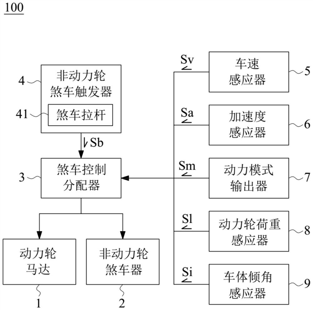
[0003] The purpose of the present invention is to solve various problems of known brake systems, and propose a variable linkage brake system for electric locomotives

Method used


Image

  • Variable Linkage Braking System of Electric Locomotive

Examples


Embodiment Construction

[0038] In order to fully understand the present invention, the present invention will be described in detail through the following specific embodiments and accompanying drawings. Those skilled in the art can understand the purpose, features and effects of the present invention from the content disclosed in this specification. It should be noted that the present invention can be implemented or applied through other different specific embodiments, and various modifications and changes can be made to the details in this specification based on different viewpoints and applications without departing from the spirit of the present invention. . In addition, the appended drawings of the present invention are only for simple illustration, and are not drawn according to the actual size. The following embodiments will further describe the relevant technical content of the present invention in detail, but the disclosed content is not intended to limit the claims of the present invention....


PUM


Abstract

The present invention discloses a variable linkage braking system of an electric locomotive, including a power wheel motor, non-powered wheel brake, a brake control dispenser, and a non-powered wheelbrake trigger, the brake control distributor is in signal connection with the power wheel motor and the non-power wheel brake, the non-power wheel brake trigger signal is connected with the brake control distributor, and the brake control distributor outputs the ratio of the braking resistance of the power wheel and the braking resistance of the non-power wheel. According to the variable type linkage braking system of the electric locomotive, different braking ratios can be distributed according to various real-time vehicle conditions, and more excellent braking performance and stability can be achieved.

Description

technical field [0001] The invention relates to a braking system, more particularly to a variable linkage braking system of an electric locomotive. Background technique [0002] Front and rear linkage braking system (CBS, Combination Braking System) allows the rider to brake, as long as the left or right side of the brake is applied, the front and rear wheels can be braked at the same time, reducing the risk of slipping or rollover caused by single-wheel braking. In other words, CBS can decelerate the front and rear wheels at the same time, maintain the stability of the fuselage, and reduce the chance of rear wheel slippage. However, the most criticized aspect of traditional linkage brakes is that the front and rear brakes are mechanical and the distribution ratio of the front and rear brakes is fixed and cannot be changed, which cannot satisfy the braking habits of all users. Contents of the invention [0003] The purpose of the present invention is to solve various prob...

Claims


Application Information

Patent Timeline
Patent Type & Authority Applications(China)
IPC IPC(8): B62L1/02B62L3/08B62M6/40B62M6/50B62J45/412B62J45/415B62J45/00
CPCB62J99/00B62L1/02B62L3/08B62M6/40B62M6/50
Inventor 许理彦郑凯文
Owner OTTOBIKE CO LTD
Learn More