
Anti-unhooking mechanism for tower crane hoisting

A decoupling and arc-shaped technology, which is applied in the field of anti-decoupling mechanisms for tower cranes, can solve problems such as low safety factor, material falling off, and material damage, and achieve the effects of improved stability, good detachment prevention effect, and simple structure

Active Publication Date: 2021-01-05
HUADONG BUILDING CO LTD OF CHINA CONSTR FIFTH ENG BUREAU
View PDF7 Cites 7 Cited by
  • Summary
  • Abstract
  • Description
  • Claims
  • Application Information

AI Technical Summary

Problems solved by technology

[0004] The purpose of the present invention is to solve the disadvantages in the prior art that materials fall off due to shaking during transportation, which not only causes damage to materials, wastes resources, increases costs, but also easily hurts people and has a low safety factor. , and a tower crane hoisting anti-coupling mechanism proposed

Method used


Image

  • Anti-unhooking mechanism for tower crane hoisting
  • Anti-unhooking mechanism for tower crane hoisting
  • Anti-unhooking mechanism for tower crane hoisting

Examples


Embodiment 1

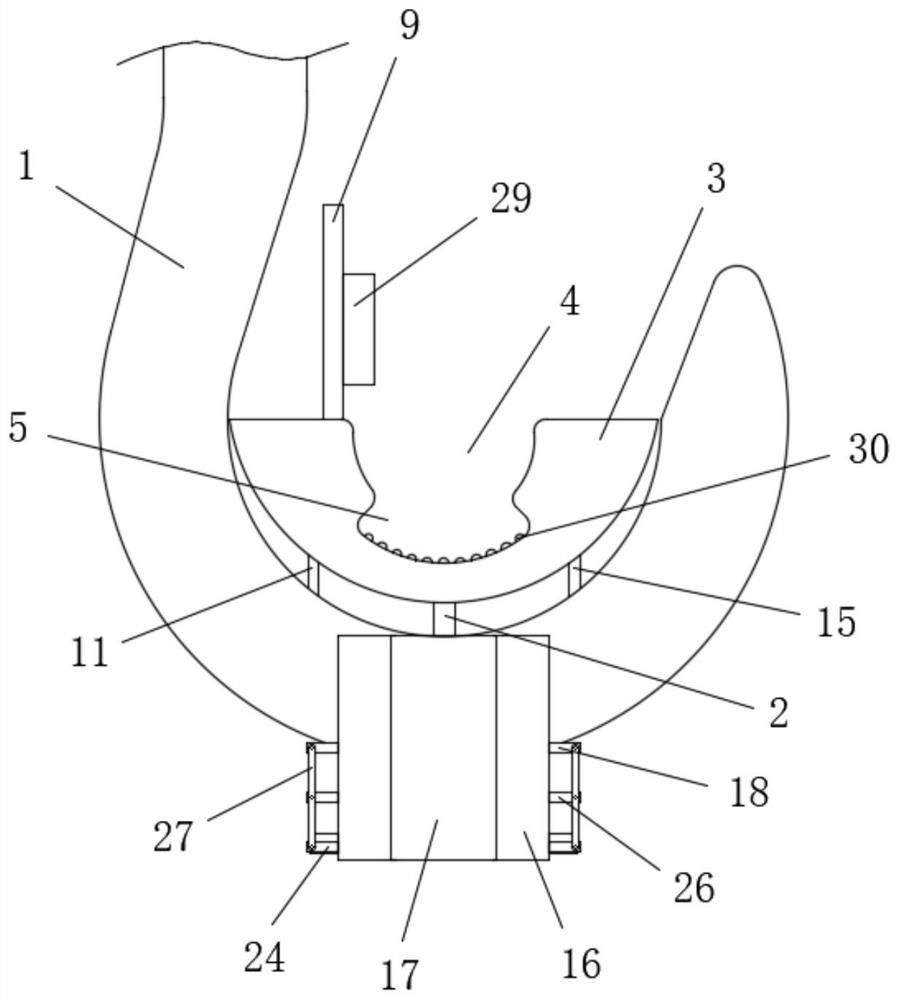
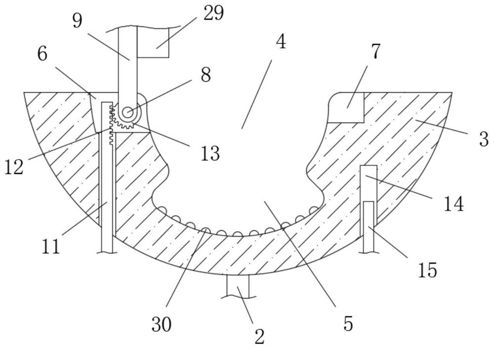
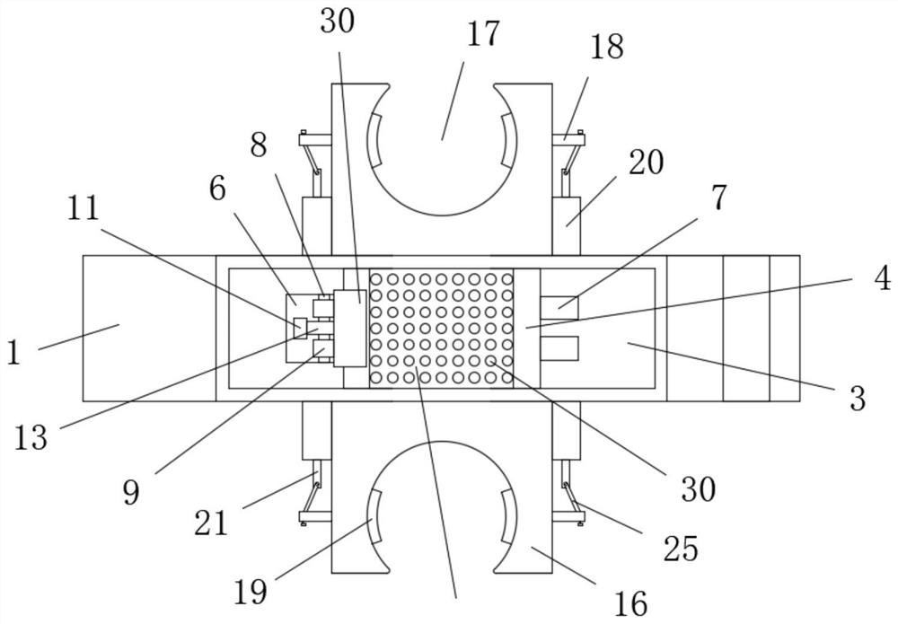
[0027] refer to Figure 1-7 , an anti-drop hook mechanism for tower hoisting, comprising a hook 1, the bottom of the hook 1 is slidably connected with a movable rod 2, the top of the movable rod 2 extends to the top of the hook 1 and is fixedly connected with an arc-shaped movable block 3, and the arc-shaped The bottom radian of the movable block 3 is adapted to the top radian of the hook 1. The top of the arc-shaped movable block 3 is flat and is provided with an arc-shaped slot 4. The bottom inner wall of the arc-shaped slot 4 is provided with a lanyard placement slot 5. The arc-shaped The top side of the movable block 3 is provided with an installation groove 6, and the interior of the installation groove 6 is rotatably connected with a rotating shaft 8, and two limit rods 9 are symmetrically fixed on the rotating shaft 8, and the other side of the top of the arc-shaped movable block 3 is symmetrical There are two limit slots 7, the installation slot 6 and the two limit slo...

Embodiment 2

[0029]Further improved on the basis of Embodiment 1: the bottom inner wall of the installation groove 6 is penetrated with a transmission rod 11, and the bottom end of the transmission rod 11 extends below the arc-shaped movable block 3 and is fixedly connected with the top side of the hook 1. One side top of the rod 11 is provided with a tooth groove 12, and one side of the rotating shaft 8 is fixedly sleeved with a half gear 13 located between the two limit rods 9, and the half gear 13 is meshed with the tooth groove 12, and when the arc moves When the block 3 moves up and down and drives the half gear 13 to move up and down, the rotating shaft 8 can be driven to rotate through the meshing motion with the tooth groove 12, and the bottom of the arc-shaped movable block 3 is provided with a chute 14 on the side away from the drive rod 11, the chute 14 is slidably connected with a support rod 15, and the bottom end of the support rod 15 extends below the arc-shaped movable block...


PUM


Abstract

The invention belongs to the technical field of tower crane equipment, particularly relates to an anti-unhooking mechanism for tower crane hoisting, and aims to solve the problems of material damage,resource waste, cost increase and high possibility of injuring people due to material falling caused by shaking generated in a transportation process in the prior art. With adoption of the scheme, theanti-unhooking mechanism for tower crane hoisting comprises a hook, wherein a movable rod is slidably connected to the bottom of the hook in a penetrating mode; the top end of the movable rod extendsto a position above the hook and is fixedly connected to an arc-shaped movable block; the bottom radian of the arc-shaped movable block is matched with the top radian of the hook; the top of the arc-shaped movable block is a plane and provided with an arc-shaped groove, and a hanging rope placing groove is formed in the inner wall of the bottom of the arc-shaped groove. The anti-unhooking mechanism is simple in structure, can automatically clamp or loosen a hanging rope through changes of gravity without bounding or unbounding the hanging rope, is good in the anti-unhooking effect, greatly improves safety and practicability, and is beneficial for application and popularization.

Description

technical field [0001] The invention relates to the technical field of tower crane equipment, in particular to an anti-hook mechanism for tower crane hoisting. Background technique [0002] Tower cranes are the most commonly used lifting equipment on construction sites, also known as "tower cranes". Corrugated, concrete, steel pipe and other construction raw materials, in order to reduce the labor force and reduce the construction cost at the same time, so the tower crane is an indispensable equipment on the construction site, and the hook is an important part of the tower crane to suspend the material. [0003] The structure of the traditional tower crane hook is simple, and there is no protective mechanism except the hanging material. During the transportation of the material, the shaking caused by the material easily causes the material to fall off, which not only causes the material to be damaged, wastes resources, increases the cost, and is prone to smashing and injurin...

Claims


Application Information

Patent Timeline
Patent Type & Authority Applications(China)
IPC IPC(8): B66C1/34B66C1/36
CPCB66C1/34B66C1/36Y02E10/72
Inventor 项钰鲍佳陈亚杰
Owner HUADONG BUILDING CO LTD OF CHINA CONSTR FIFTH ENG BUREAU
Learn More