Hydrolytic acidification reaction tank for sewage treatment

A technology for hydrolytic acidification and sewage treatment, which is applied in biological water/sewage treatment, water/sludge/sewage treatment, biological treatment devices, etc. It can solve the problems of affecting the progress of hydrolytic acidification reaction, energy absorption buffer, and the loss of diversion in the diversion table. , to avoid enlarged extrusion overlap and increase the flow rate

Inactive Publication Date: 2021-01-05
潘东强
View PDF0 Cites 4 Cited by
  • Summary
  • Abstract
  • Description
  • Claims
  • Application Information

AI Technical Summary

Problems solved by technology

[0003] In view of the above, because the sludge is affected by the height between the feed inlet and the diversion platform, the weight of the sludge falling on the diversion platform cannot be the same. The hedging is formed on the inclined surface, so that the inclined surface cannot effectively absorb energy and buffer when it is hit, and the surface of the inclined surface is smashed into pits of different depths, and the sludge falling on the inclined surface will be everywhere in a unit time. Random splashing aggravates the abrasion of the sludge on the surface of the diversion table, causing the sludge accumulation surface to expand, squeeze and overlap, and make its inclined surface gradually become flat, resulting in the loss of the diversion function of the diversion table and seriously affecting the hydrolysis. Acidification reaction progress problem, the present invention provides a hydrolysis acidification reaction pool for sewage treatment

Method used


Image

  • Hydrolytic acidification reaction tank for sewage treatment
  • Hydrolytic acidification reaction tank for sewage treatment
  • Hydrolytic acidification reaction tank for sewage treatment

Examples


Embodiment 1

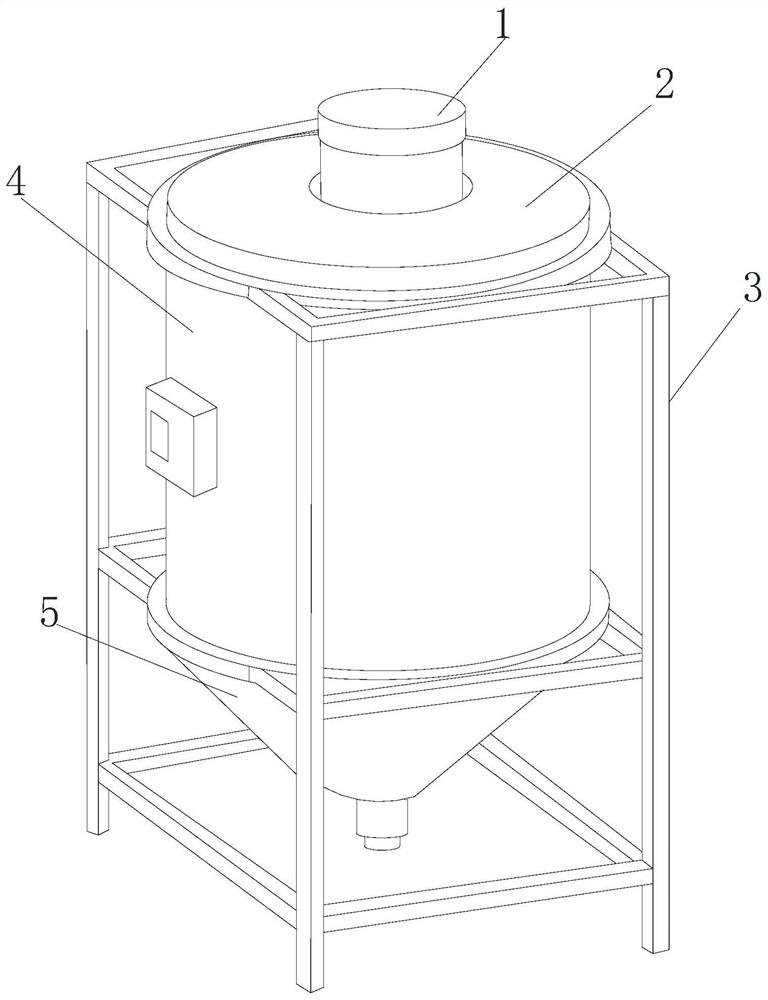
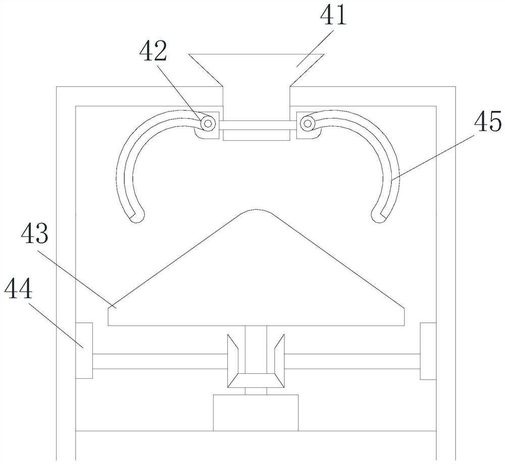
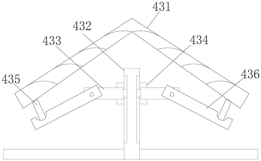
[0030] Such as Figure 1-Figure 4 As shown, the present invention provides a hydrolysis acidification reaction tank for sewage treatment. The middle part of the cover 2 communicates with the inside of the reaction device 4. The outside of the reaction device 4 is covered with a support frame 3, and the bottom is fixedly connected with a centralized acidification place 5. The reaction device 4 includes a feed port 41 and a cyclocross device 42. , shunt structure 43, top support 44, stirring hook angle 45, the feed inlet 41 and the feed pipe 1 are connected to each other, and the bottom thereof is movably matched with the stirring hook angle 45 through the ring crosser 42, and the stirring The hook angle 45 interferes with the gap at the top of the diversion structure 43, and the bottom is welded to the top support member 44. The diversion structure 43 includes a conversion device 431, a fixed rod 432, a fitting block 433, a sleeve 434, a support device 435, and a guide Rod 436...

Embodiment 2

[0032] Such as Figure 5-Figure 7 As shown, on the basis of Embodiment 1, the present invention combines the mutual cooperation of the following structural components. The support device 435 includes an anti-collision device 351, a gathering bolt 352, a limit part 353, a pair of bars 354, a sleeve 355, a buckle Closing ring 356, the anti-collision device 351 is a hemispherical structure, which is arranged on both sides of the bottom of the anti-accumulation long road 312 and the anti-accumulation short road 315, and is welded to the pair of bars 354. Embedded in the inner circumferential groove of the sleeve 355, the fastening ring 356 is movably engaged in the middle of the gathering bolt 352, and the limiting part 353 is fixedly connected between the two sleeves 355, and the gathering bolt 352 and the fastening The ring 356 is inserted into the inner circumferential groove of the sleeve 355 through the limiting part 353, and a triangular structure is formed between the three...


PUM


Abstract

The invention discloses a hydrolytic acidification reaction tank for sewage treatment, which structurally comprises a feeding pipe, a reaction cover, a bracket frame, a reaction device and a centralized acidification part, the feeding pipe is inserted in the middle of the reaction cover and is communicated with the interior of the reaction device, the reaction device is sleeved with the bracket frame, and the bottom of the reaction device is fixedly connected with the centralized acidification part; shaking deformation is carried out in the fixed range of gathering bolts between limiting parts, so that a conversion device fluctuates intermittently, a sludge accumulation surface is prevented from being expanded, extruded and overlapped, the inclined surface of the conversion device surfaceis gradually changed into a plane shape, and when sludge with different sizes falls onto the inclined surface of the conversion device, a supporting device at the bottom of the conversion device can make the conversion device fluctuate up and down through high-speed rotation under the bolt connection matching effect of attaching blocks, the effective energy absorption and buffering effect is achieved, pits with different depths cannot be formed in the surface of the inclined face, and equipment internal functional components are not damaged.

Description

technical field [0001] The invention relates to the field of sewage treatment, in particular to a hydrolysis acidification reaction pool for sewage treatment. Background technique [0002] The hydrolysis treatment method is a method between aerobic and anaerobic treatment methods, and the combination with other processes can reduce the treatment cost and improve the treatment efficiency. The existing hydrolysis acidification reaction tank has a simple structure, and the sludge is prone to concentrated accumulation, thus The decomposition efficiency is reduced, and a diversion table with a conical structure is usually used to solve this problem, but since the sludge is affected by the height between the feed inlet and the diversion table, the weight of the sludge falling on the diversion table is impossible Similarly, the sludge hits the inclined surface of the diverter table at a high flow rate, and forms a hedge against the inclined surface, resulting in the inability of th...

Claims


Application Information

Patent Timeline
Patent Type & Authority Applications(China)
IPC IPC(8): C02F3/00
CPCC02F3/00C02F2203/006
Inventor 潘东强
Owner 潘东强
Why Eureka
Try Eureka