Transporting and burying device for burying underground pipelines

A technology for underground pipelines and connecting blocks, which is applied in pipeline laying and maintenance, lifting devices, mechanical equipment, etc., and can solve problems such as inconvenient operation and large effort

Inactive Publication Date: 2021-01-05
陈佳
View PDF7 Cites 3 Cited by
  • Summary
  • Abstract
  • Description
  • Claims
  • Application Information

AI Technical Summary

Problems solved by technology

[0005] In order to overcome the disadvantages of labor-intensive transportation and inconvenient operation, the technical problem of the present invention is to provide a labor-saving and easy-to-operate transportation and embedding device for underground pipeline embedding

Method used


Image

  • Transporting and burying device for burying underground pipelines
  • Transporting and burying device for burying underground pipelines
  • Transporting and burying device for burying underground pipelines

Examples


Embodiment 1

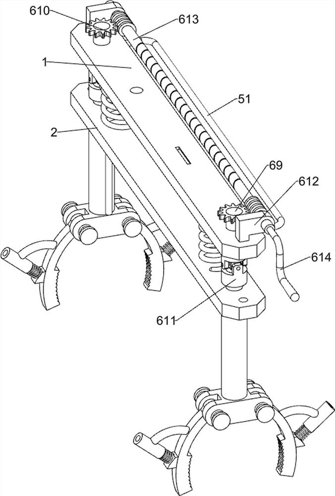
[0022] Such as Figure 1-3 with Figure 5 As shown, a transportation and embedding device for underground pipeline burial includes upper board 1, lower board 2, first connecting block 3, bent rod 4, wheels 5, handle 51, lowering and raising mechanism 6 and hydraulic pushing mechanism 7. There is a lower board 2 under the upper board 1 and a slot and a square hole are opened on the upper right side of the upper board 1. The first connecting block 3 is arranged at both ends of the lower board 2, and the first connecting block 3 is two Both sides are provided with curved rods 4, and the lower ends of the curved rods 4 are provided with wheels 5, and the rear side of the upper board 1 is provided with a handle 51, and the upper board 1 is provided with a descending mechanism 6, and the upper board 1 and the lower board 2 A hydraulic push mechanism 7 is arranged between them.

[0023] The descending and ascending mechanism 6 includes a screw mandrel 61, a threaded cylinder 62, a ...

Embodiment 2

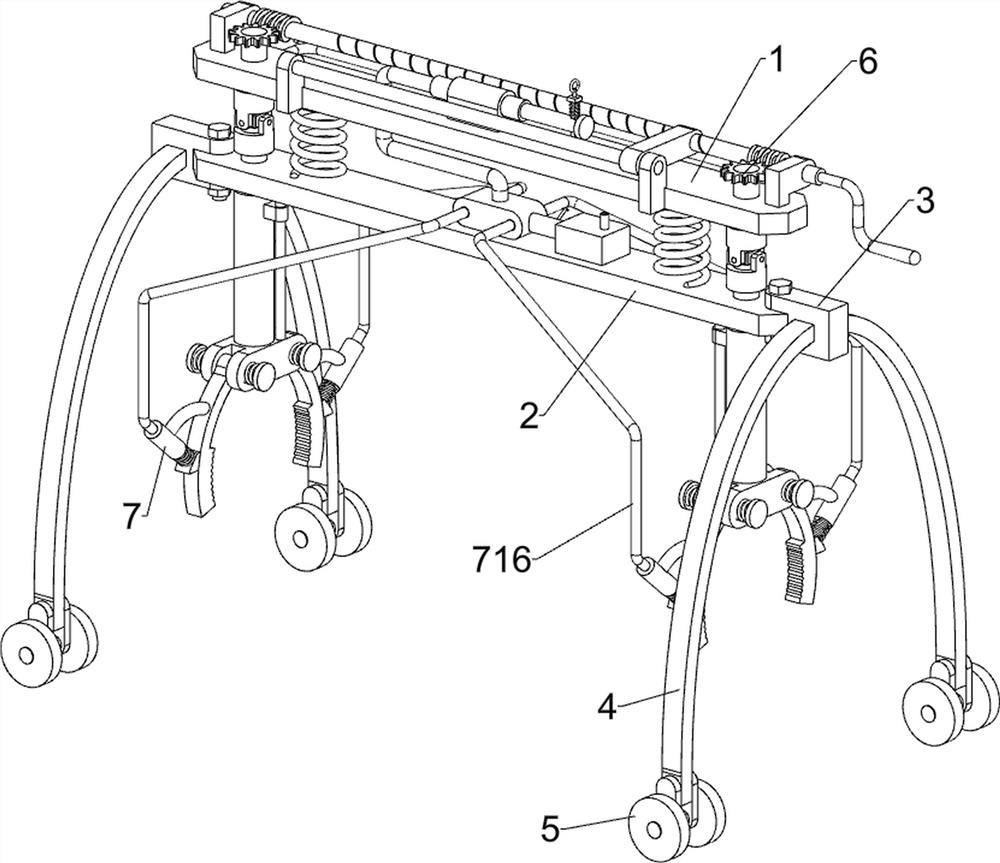
[0027] Such as Figure 4 As shown, on the basis of Embodiment 1, a transportation and embedding device for underground pipeline embedding also includes a second fixing base 8, a second guide post 9 and a nut block 10, and the upper front side of the upper vehicle plate 1 is about the upper The center line of the car plate 1 is symmetrically provided with a second fixed seat 8, and a second guide post 9 is arranged between the second fixed seats 8, and a nut block 10 is slidably arranged on the second guide post 9, and the rear side of the nut block 10 is connected to the transmission shaft. 613 central thread fits.

[0028] In the process of rotating the transmission shaft 613, the rotation of the transmission shaft 613 will cause the nut block 10 to move in the direction close to the second piston rod 78 on the second guide post 9, and when the nut block 10 moves a certain distance, the nut block 10 will push the first Two piston rods 78 squeeze the hydraulic oil in the seco...


PUM


Abstract

The invention relates to a transporting and burying device, in particular to a transporting and burying device for burying underground pipelines. The transporting and burying device for burying the underground pipelines saves labor and is easy and convenient to operate. The transporting and burying device for burying the underground pipelines comprises an upper vehicle plate, first connecting blocks, bent rods, wheels, a handle and a descending and ascending mechanism, wherein a lower vehicle plate is arranged below the upper vehicle plate, and a linear groove and a square hole are formed in one side of the upper vehicle plate; the first connecting blocks are arranged at the two ends of the lower vehicle plate; the bent rods are arranged on the two sides of the first connecting blocks; thewheels are arranged at the lower ends of the bent rods; the handle is arranged on one side of the upper vehicle plate; A worker rotates a transmission shaft, then second connecting blocks drive clamping blocks to move downwards together, and when the clamping blocks are located on the two sides of a pipeline, the worker pushes a second piston column to compress hydraulic oil in a second cylinderbody, so that the clamping blocks rotate around a connecting shaft to clamp the water pipeline.

Description

technical field [0001] The invention relates to a transport embedding device, in particular to a transport embedding device for underground pipeline embedding. Background technique [0002] Underground pipelines are pipelines buried underground for transporting liquids, gases or loose solids. Modern underground pipes come in a variety of varieties, most of which are constructed of materials such as steel, cast iron, plastic, and fiberglass (reinforced plastic). [0003] In modern urban construction, underground pipelines are the blood of a city, especially sewer pipelines and underground pipelines for transporting natural gas. When laying underground pipelines, workers must first dig a buried pit on the ground, and then move the underground pipelines Bury the hole, and finally fill it with soil. At present, manual handling of underground pipelines has the problems of requiring a lot of effort and inconvenient operation. [0004] Therefore, a labor-saving and easy-to-opera...

Claims


Application Information

Patent Timeline
Patent Type & Authority Applications(China)
IPC IPC(8): F16L1/028F16L1/06B66F11/00F16F15/067
CPCB66F11/00F16F15/067F16L1/028F16L1/06F16L1/065
Inventor 陈佳
Owner 陈佳
Why Eureka
Try Eureka