A driving method and system for a legged robot controlled by a hydraulic drive unit sliding mode

A driving unit and driving method technology, applied in general control system, control/regulation system, adaptive control and other directions, can solve the problems of poor control effect of robot motion performance, difficult to obtain gain parameters, and robot prone to chattering, etc. Achieve the effect of improving the underlying control performance, improving the position servo control performance, and alleviating the chattering phenomenon

Active Publication Date: 2021-11-30
YANSHAN UNIV
View PDF5 Cites 0 Cited by
  • Summary
  • Abstract
  • Description
  • Claims
  • Application Information

AI Technical Summary

Problems solved by technology

[0004] ①In sliding mode control, when the system state trajectory reaches the sliding mode surface, it is difficult to slide strictly along the sliding mode surface to the equilibrium point, but to approach the equilibrium point by crossing back and forth on both sides, and the robot is prone to chattering;
[0005] ②When using the pole configuration method to calculate the sliding mode surface parameters, the expected poles of the system need to be known, but for high-order systems, a large amount of engineering practice experience is required to obtain the expected poles of the system, which increases the difficulty of the application of this method;
[0006] ③ Adding an extended state observer to the sliding mode control can reduce the influence of the system disturbance on the control performance in the approaching stage, but the extended state observer is greatly affected by the sensor noise, resulting in poor control of the robot's motion performance, and the gain parameters are not easy to control. ask for

Method used


Image

  • A driving method and system for a legged robot controlled by a hydraulic drive unit sliding mode
  • A driving method and system for a legged robot controlled by a hydraulic drive unit sliding mode
  • A driving method and system for a legged robot controlled by a hydraulic drive unit sliding mode

Examples


Embodiment Construction

[0114] The following will clearly and completely describe the technical solutions in the embodiments of the present invention with reference to the accompanying drawings in the embodiments of the present invention. Obviously, the described embodiments are only some, not all, embodiments of the present invention. Based on the embodiments of the present invention, all other embodiments obtained by persons of ordinary skill in the art without making creative efforts belong to the protection scope of the present invention.

[0115] In order to make the above objects, features and advantages of the present invention more comprehensible, the present invention will be further described in detail below in conjunction with the accompanying drawings and specific embodiments.

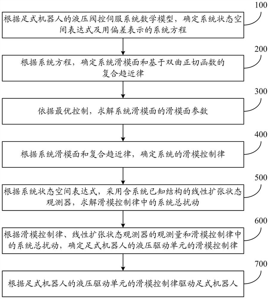
[0116] figure 1 It is a schematic flow chart of the driving method of the legged robot controlled by the sliding mode of the hydraulic drive unit of the present invention. Such as figure 1 As shown, the footed r...


PUM


Abstract

The invention relates to a driving method and system for a legged robot controlled by a sliding mode of a hydraulic driving unit. The method includes: according to the mathematical model of the hydraulic valve control servo system of the legged robot, determine the system state space expression and the system equation represented by the deviation; according to the system equation, determine the system sliding mode surface and the compound approach based on the hyperbolic tangent function According to the optimal control, solve the sliding mode surface parameters of the sliding mode surface of the system; determine the sliding mode control law of the system according to the sliding mode surface of the system and the compound reaching law; according to the state space expression of the system, use the known structure of the system The linear expansion state observer of the linear expansion state observer solves the total disturbance of the system in the sliding mode control law; determines the sliding mode control law of the hydraulic drive unit of the legged robot; drives the legged robot according to the sliding mode control law of the hydraulic drive unit of the legged robot. The invention can optimize the driving effect of the legged robot.

Description

technical field [0001] The invention relates to the field of electro-hydraulic servo control, in particular to a driving method and system for a legged robot controlled by a sliding mode of a hydraulic drive unit. Background technique [0002] The hydraulic-driven legged robot has the dual advantages of hydraulic drive and legged robot, specifically: the robot has a strong load-bearing capacity, fast response speed, and can adapt to various unknown and unstructured environments, such as grass, snow, mountains, etc. The excellent performance makes it have a wide range of application prospects in industries such as rescue and material delivery, and has become a research focus in the field of robotics. The movement of each joint of the leg of this type of robot is generally driven by a highly integrated valve-controlled cylinder (referred to as the hydraulic drive unit). The control of the hydraulic drive unit belongs to the bottom-level control of the robot, and its control pe...

Claims


Application Information

Patent Timeline
Patent Type & Authority Patents(China)
IPC IPC(8): G05B13/04
CPCG05B13/042
Inventor 俞滨朱琦歆黄敦浩王春雨巴凯先孔祥东
Owner YANSHAN UNIV
Why Eureka
Try Eureka