Foot type robot driving method and system controlled by hydraulic driving unit sliding mode

A technology of driving unit and driving method, which is applied in the general control system, control/regulation system, adaptive control, etc., and can solve problems such as slippage, difficulty in obtaining gain parameters, and increasing difficulty in method application

Active Publication Date: 2021-01-05
YANSHAN UNIV
View PDF6 Cites 1 Cited by
  • Summary
  • Abstract
  • Description
  • Claims
  • Application Information

AI Technical Summary

Problems solved by technology

[0004] ①In sliding mode control, when the system state trajectory reaches the sliding mode surface, it is difficult to slide strictly along the sliding mode surface to the equilibrium point, but to approach the equilibrium point by crossing back and forth on both sides, and the robot is prone to chattering;
[0005] ②When using the pole configuration method to calculate the sliding mode surface parameters, the expected poles of the system need to be known, but for high-order systems, a large amount of engineering practice experience is required to obtain the expected poles of the system, which increases the difficulty of the application of this method;
[0006] ③ Adding an extended state observer to the sliding mode control can reduce the influence of the system disturbance on the control performance in the approaching stage, but the extended state observer is greatly affected by the sensor noise, resulting in poor control of the robot's motion performance, and the gain parameters are not easy to control. ask for

Method used


Image

  • Foot type robot driving method and system controlled by hydraulic driving unit sliding mode
  • Foot type robot driving method and system controlled by hydraulic driving unit sliding mode
  • Foot type robot driving method and system controlled by hydraulic driving unit sliding mode

Examples


Embodiment Construction

[0114]The technical solutions in the embodiments of the present invention will be clearly and completely described below in conjunction with the accompanying drawings in the embodiments of the present invention. Obviously, the described embodiments are only a part of the embodiments of the present invention, rather than all the embodiments. Based on the embodiments of the present invention, all other embodiments obtained by those of ordinary skill in the art without creative work shall fall within the protection scope of the present invention.

[0115]In order to make the above objectives, features and advantages of the present invention more obvious and understandable, the present invention will be further described in detail below in conjunction with the accompanying drawings and specific embodiments.

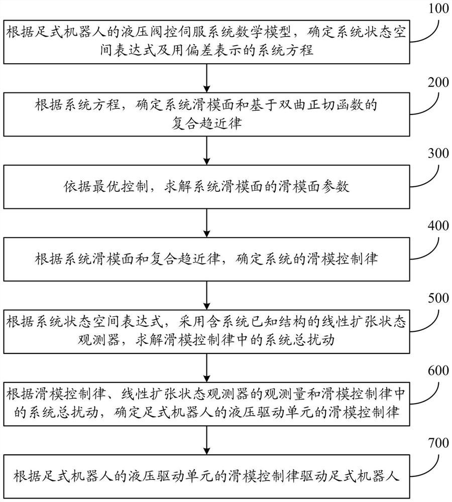
[0116]figure 1 It is a schematic flow chart of a foot robot driving method controlled by a sliding mode of a hydraulic driving unit of the present invention. Such asfigure 1 As shown, th...


PUM


Abstract

The invention relates to a foot type robot driving method and system controlled by a hydraulic driving unit sliding mode. The method comprises the following steps: determining a system state space expression and a system equation expressed by deviation according to a mathematical model of a hydraulic valve control servo system of the foot-type robot; determining a system sliding mode surface and acomposite reaching law based on a hyperbolic tangent function according to a system equation; solving sliding mode surface parameters of the system sliding mode surface according to the optimal control; determining a sliding mode control law of the system according to the sliding mode surface of the system and the composite reaching law; according to the system state space expression, adopting alinear extended state observer containing a known structure of the system to solve system total disturbance in the sliding mode control law; determining a sliding mode control law of a hydraulic driving unit of the foot-type robot; and driving the foot-type robot according to the sliding mode control law of the hydraulic driving unit of the foot-type robot. The driving effect of the foot-type robot can be optimized.

Description

Technical field[0001]The invention relates to the field of electro-hydraulic servo control, in particular to a method and system for driving a footed robot controlled by a hydraulic drive unit sliding mode.Background technique[0002]Hydraulically driven footed robots have the dual advantages of hydraulic driven and footed robots. The specific performance is: the robot has strong load-bearing ability, fast response speed and can adapt to various unknown, non-structural environments, such as grass, snow, mountains, etc. Excellent performance makes it have a wide range of application prospects in rescue, material transportation and other industries, and has become a research focus in the field of robotics. The joint motions of the legs of this type of robot are generally driven by highly integrated valve-controlled cylinders (referred to as hydraulic drive units). The control of the hydraulic drive unit belongs to the bottom-level control of the robot. Its control performance affects th...

Claims


Application Information

Patent Timeline
IPC IPC(8): G05B13/04
CPCG05B13/042
Inventor 俞滨朱琦歆黄敦浩王春雨巴凯先孔祥东
Owner YANSHAN UNIV
Why Eureka
Try Eureka