
System fault injection method, injection device and storage medium

A system failure and injection device technology, applied in the computer field, can solve problems such as inaccurate evaluation results and unsmooth fault injection process, and achieve the effect of solving inaccurate evaluation results and achieving accuracy

Pending Publication Date: 2021-01-05
CHINA ACAD OF LAUNCH VEHICLE TECH
View PDF5 Cites 2 Cited by
  • Summary
  • Abstract
  • Description
  • Claims
  • Application Information

AI Technical Summary

Problems solved by technology

[0004] The present invention proposes a system fault injection method, injection device and storage medium, aiming to solve the problem of inaccurate evaluation results caused by fault injection process in most fault testing technologies in the prior art

Method used


Image

  • System fault injection method, injection device and storage medium
  • System fault injection method, injection device and storage medium
  • System fault injection method, injection device and storage medium

Examples


Embodiment 1

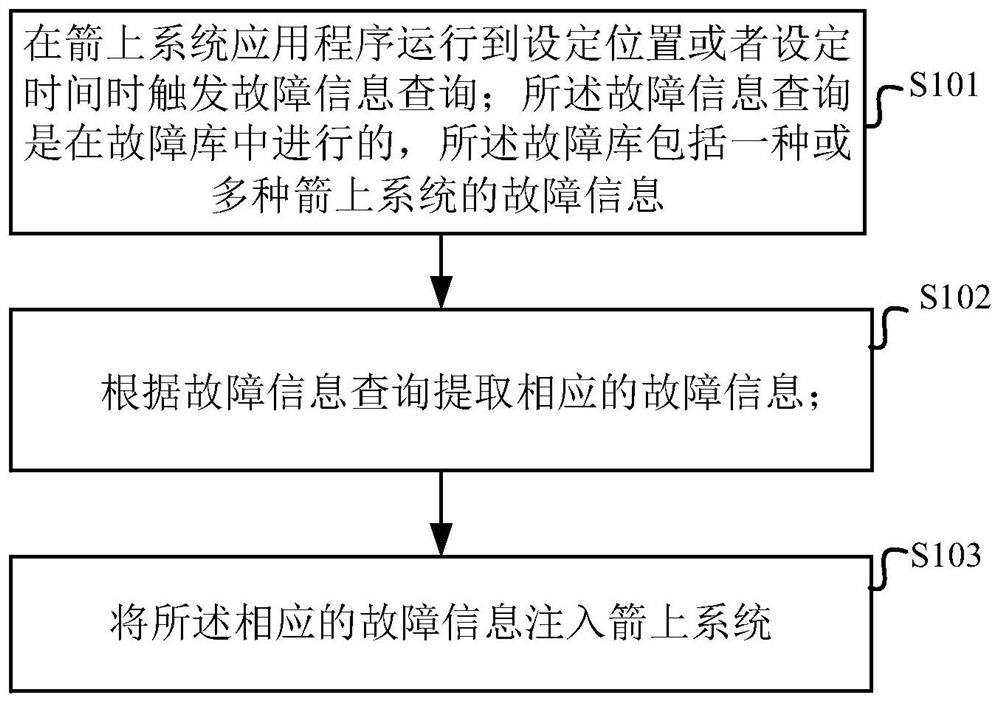
[0027] figure 1 A flow chart of steps of a system fault injection method according to an embodiment of the present application is shown in FIG.

[0028] Such as figure 1 As shown, the system fault injection method includes the following steps:

[0029] S101, triggering a fault information query when the arrow system application program runs to a set position or a set time. Wherein, the fault information query is carried out in the fault database, and the fault database includes fault information of one or more systems on the arrow.

[0030] S102. Extract corresponding fault information according to the fault information query.

[0031] S103. Inject the corresponding fault information into the arrow system.

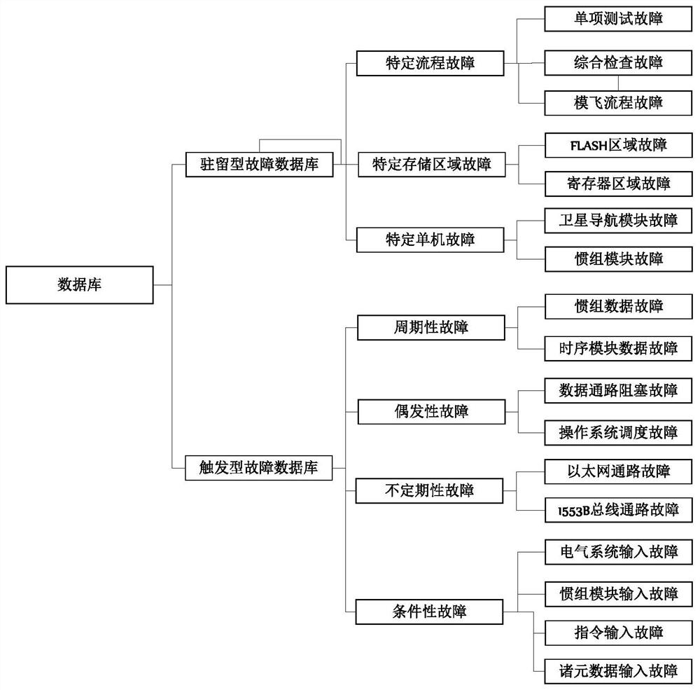
[0032] figure 2 A design diagram of a fault library according to an embodiment of the present application is shown in .

[0033] Specifically, such as figure 2 As shown, the fault library includes:

[0034] a resident fault database storing fault information at a...

Embodiment 2

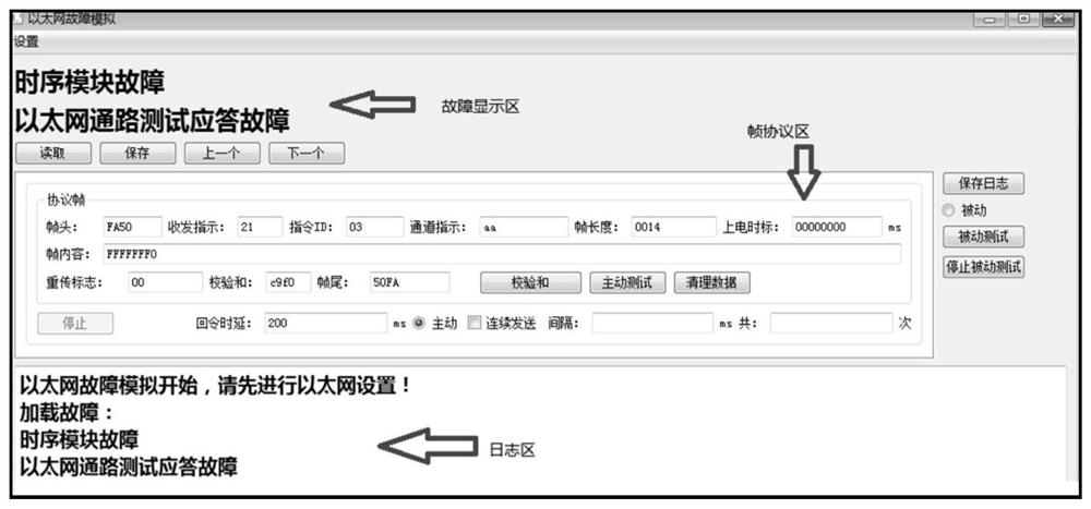
[0075] Figure 4 A schematic diagram of a fault generation interface according to an embodiment of the present application is shown in .

[0076] Such as Figure 4 As shown, the system fault injection device specifically includes:

[0077] The fault triggering module 10 is used for triggering fault information inquiry when the arrow system application program runs to a set position or a set time. Wherein, the fault information query is carried out in the fault database, and the fault database includes fault information of one or more systems on the arrow;

[0078] Fault extraction module 20, for extracting corresponding fault information according to the fault information query;

[0079] The fault injection module 30 is configured to inject the corresponding fault information into the arrow system.

[0080] After the fault is generated, it is stored in the database. The resident fault database mainly stores faults at specific locations, including faults that occur when the...


PUM


Abstract

The embodiment of the invention provides a system fault injection method, an injection device and a storage medium. The system fault injection method triggers fault information query when an on-rocketsystem application program runs to a set position or set time, the fault information query is carried out in a fault library, the fault library comprises fault information of one or more rocket-bornesystems, then corresponding fault information is queried and extracted according to the fault information, and finally the corresponding fault information is injected into a rocket-borne system. Under the condition of guaranteeing the fault requirement and the generation requirement, a fault is triggered to be extracted and injected when the rocket-borne system operates at the specific operationposition or within the set time, so that the fault is smoothly injected into the rocket-borne system, and the accuracy of fault evaluation is realized. The problem that in the prior art, the evaluation result is inaccurate due to the fact that the fault injection process is not smooth is solved.

Description

technical field [0001] The present application belongs to the field of computer technology, and in particular relates to a system fault injection method, injection device and storage medium. Background technique [0002] Reliability is an important index to measure the performance of the rocket control system. Fault-tolerant technology utilizes the redundancy of hardware, software, time, and information to realize the shielding of errors that occur during system operation. Fault-tolerant technology is the main factor to ensure system reliability. technology. The current rocket control systems adopt fault-tolerant mechanisms to varying degrees to ensure the reliability of the system, forming a widely used fault-tolerant system. Among them, fault testing technology is an effective method to evaluate system reliability. Fault testing technology accelerates system failure by artificially introducing faults into the system. The fault injection process involves classifying fault...

Claims


Application Information

Patent Timeline
Patent Type & Authority Applications(China)
IPC IPC(8): G06F11/22
CPCG06F11/2273G06F11/2205
Inventor 张亚琳胡骁李浩张雪婷潘彦鹏陈旭东吕瑞涂海峰严大卫陈喆葛云鹏梁卓宋志国龚旻王冀宁杨立杰谭黎立李烨丁禹赵楠陈铁凝郝仁杰邱岳诗孟文霞王凯旋李迎博薛晨琛姜春旺杜肖谭清科刘谷均冯泽明
Owner CHINA ACAD OF LAUNCH VEHICLE TECH
Learn More