
Pipeline arrangement method based on BIM model

A pipeline layout and model technology, applied in special data processing applications, instruments, electrical and digital data processing, etc., can solve problems such as drawing errors, pipeline collisions, and inability to realize real-time information transmission, and achieve the goal of reducing deviation and reducing rework costs. Effect

Inactive Publication Date: 2021-01-05
KUNMING RAILWAY CONSTR COMPANY OF CHINA RAILWAY NO 8 ENG GRP +1
View PDF5 Cites 9 Cited by
  • Summary
  • Abstract
  • Description
  • Claims
  • Application Information

AI Technical Summary

Problems solved by technology

[0003] The current pipeline layout mode mostly stays on two-dimensional drawings. For the pipeline layout of houses with large engineering volume, complicated procedures and many types of pipelines, it is difficult to achieve comprehensive overall planning and refined management in on-site construction management.
At the same time, since the construction of various pipelines is independent of each other, such as water pipes, air pipes, and wire pipes, the drawings are drawn separately, resulting in no interlinkage of information between various disciplines, and the real-time transmission of information cannot be realized. The horizontal spacing is controlled by the cross section, but the vertical spacing is difficult to control in the design stage. Therefore, in the actual construction process, after some pipelines are laid in the early stage, the pipelines laid in the later period may collide with the previous pipelines, making it difficult to accurately control; and When CAD draws 2D drawings, multiple engineers are required to design, and the data cannot be cross-referenced in real time, resulting in inevitable errors in the final drawings, which also has a great impact on the subsequent pipeline layout

Method used


Image

  • Pipeline arrangement method based on BIM model

Examples


Embodiment 1

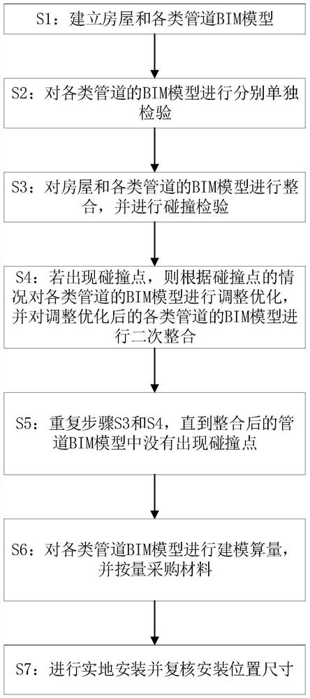
[0018] Example 1: see figure 1 The method for arranging pipelines based on a BIM model in this embodiment includes the following steps: S1: establishing BIM models of houses and various types of pipelines; S2: independently inspecting the BIM models of various types of pipelines; Integrate the BIM models of similar pipelines, and perform collision inspection; S4: If there is a collision point, adjust and optimize the BIM models of various types of pipelines according to the situation of the collision points, and carry out the adjustment and optimization of the BIM models of various types of pipelines. Secondary integration; S5: Repeat steps S3 and S4 until there is no collision point in the integrated pipeline BIM model; S6: Model and calculate various pipeline BIM models, and purchase materials according to the quantity; S7: Perform on-site installation And review the installation location size. The position of the pipeline can be pre-designed through the BIM model, problem ...

Embodiment 2

[0020] Embodiment 2: This embodiment also includes establishing a BIM model of the support and hanger, and pre-installing the support and hanger before installing the pipeline, and the support and hanger is used to fix the pipeline to the beam. It can optimize the layout of pipelines, calculate the optimal arrangement of supports and hangers in advance, and make arrangements in advance at the positions where supports and hangers need to be installed. In this embodiment, the load-bearing situation of each support and hanger and the arrangement position of each support and hanger are judged according to the BIM models of various pipelines, and then the structure of the support and hanger is designed according to the load-bearing situation and the arrangement position of the support and hanger. The structure of the installation surface at different locations is different, and the type, quantity and size of pipes at different locations are different. Therefore, it is necessary to d...

Embodiment 3

[0021] Embodiment 3: The various types of pipes in this embodiment include one or more of heating and ventilation water pipes, water supply and drainage pipes, heating and ventilation pipes, fire water pipes and smoke prevention and exhaust pipes. The drawing colors of various types of pipelines in this embodiment are different, and different pipelines are distinguished by color. In the actual construction process, a color printer is also required to print the construction drawings, which is convenient for the construction personnel to construct accurately. In step S7 of this embodiment, the installation position of the pipeline in the BIM model is corrected according to the actual construction situation, and the correction interval is ±5cm. Since the on-site construction cannot be exactly the same as the geometric dimensions given in the drawings, after construction, it is necessary to re-measure and import the actual dimensions into the BIM model for re-collision detection. ...


PUM


Abstract

The invention discloses a pipeline arrangement method based on a BIM model. The pipeline arrangement method comprises the following steps: S1, building BIM models of houses and various pipelines; S2,independently inspecting the BIM models of the various pipelines respectively; S3, integrating the BIM models of the house and various pipelines, and performing collision inspection; S4, if a collision point appears, adjusting and optimizing the BIM models of the various pipelines according to the condition of the collision point, and carrying out secondary integration on the adjusted and optimized BIM models of the various pipelines; S5, repeating the steps S3 and S4 until no collision point appears in the integrated pipeline BIM model; S6, conducting modeling calculation on the various pipeline BIM models, and purchasing materials according to the quantity; S7, carrying out on-site installation, and rechecking the installation position size. The position of the pipeline can be designed in advance through the BIM model, problem points are found in advance, the subsequent rework cost is reduced, the unified BIM model can give consideration to the size of each detail position, and the deviation of the whole project is reduced.

Description

technical field [0001] The invention relates to the field of pipeline arrangement, in particular to a pipeline arrangement method based on a BIM model. Background technique [0002] In some large buildings, various pipelines will need to be installed. Since the types, sizes and functions of pipelines are different, it is necessary to arrange various pipelines well to avoid the collision of various pipelines and prevent pipelines from colliding with each other. The space occupied by the space is large, which can save the interior space of the building. [0003] The current pipeline layout mode mostly stays on the two-dimensional drawings. For the pipeline layout of houses with large engineering volume, complex procedures and various types of pipelines, it is difficult to achieve comprehensive overall planning and refined management for on-site construction management. At the same time, since the construction of each pipeline is independent of each other, such as water pipes,...

Claims


Application Information

Patent Timeline
Patent Type & Authority Applications(China)
IPC IPC(8): G06F30/18G06F30/13G06F30/20G06F113/14
CPCG06F30/18G06F30/13G06F30/20G06F2113/14
Inventor 朱伯东许永魏焰艾涛朱未平赵军何群秀梁晓红刘薇薛连李敏
Owner KUNMING RAILWAY CONSTR COMPANY OF CHINA RAILWAY NO 8 ENG GRP
Learn More