Method for controlling boundary layer of slender revolving body to keep laminar flow flowing without separation

A technology of rotating body and boundary layer, which is applied in the direction of hull design, sustainable transportation, complex mathematical operations, etc., and can solve problems such as increasing the frictional resistance of the sailing body, increasing the pressure difference resistance, and increasing the drag of the sailing body

Active Publication Date: 2021-01-05
HEBEI HANGUANG HEAVY IND
View PDF8 Cites 0 Cited by
  • Summary
  • Abstract
  • Description
  • Claims
  • Application Information

AI Technical Summary

Problems solved by technology

[0002] When the vehicle moves in water, due to the viscosity of water, a boundary layer will be formed near its surface, such as figure 1 As shown, it is the traditional standard shape of the sailing body (a slender body of revolution), that is, a common three-section design, which is composed of an inflow section, a parallel middle body, and an outflow section, and its boundary layer is prone to transition or flow separation, resulting in an increase in the resistance of the vehicle; the resistance of the boundary layer on the vehicle is mainly divided into frictional resistance and pressure resistance, and the resistance is affected by the state of fluid movement: the boundary layer may be in the reverse pressure gradient area on the surface of the vehicle When flow separation occurs, the pressure differential resistance will increase significantly; although the turbulent boundary layer is not easy to produce flow separation, it increases the frictional resistance suffered by the vehicle

Method used


Image

  • Method for controlling boundary layer of slender revolving body to keep laminar flow flowing without separation
  • Method for controlling boundary layer of slender revolving body to keep laminar flow flowing without separation
  • Method for controlling boundary layer of slender revolving body to keep laminar flow flowing without separation

Examples


Embodiment Construction

[0061] The present invention will be described in detail below with reference to the accompanying drawings and examples.

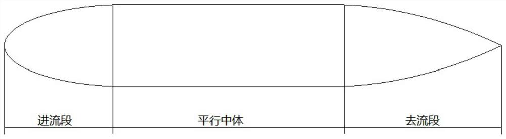
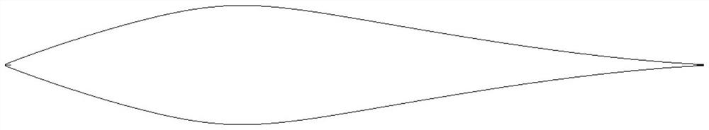
[0062] This embodiment provides a method for controlling the boundary layer of an elongated rotating body to maintain laminar non-separated flow. By optimizing the shape and surface characteristics of the elongated rotating body, the elongated rotating body can maintain laminar flow within a set speed range , to avoid flow separation or transition on the surface of the slender rotating body.

[0063] The method includes the following steps:

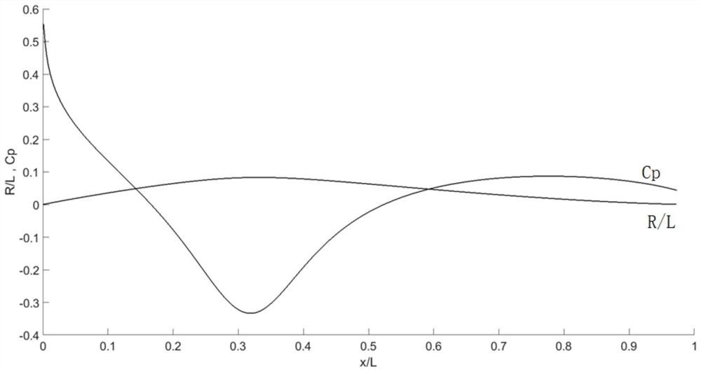
[0064] Step 1: Preset the length, slenderness ratio (take the larger value) and speed index of the slender rotating body, and obtain the potential flow equation of the surface flow field of the slender rotating body according to the slender body theory and the potential flow theory;

[0065] Specifically: because the two conditions for fluid flow separation are: (1) the fluid is viscous; (2) there is a reverse pressu...


PUM


Abstract

The invention discloses a method for controlling a boundary layer of a slender revolving body to keep laminar flow flowing without separation, relates to the technical field of fluid control, and aimsto increase the forward pressure gradient range as much as possible by optimizing the shape and surface characteristics of the slender revolving body and reduce the change rate of the fluid flowing speed in a reverse pressure gradient area. The laminar flow of the slender revolving body can be kept within a set speed range, flow separation or transition on the surface of the slender revolving body is avoided, the frictional resistance and the differential pressure resistance of the slender revolving body can be greatly reduced, and a good drag reduction effect is achieved; in addition, no extra energy is consumed while resistance reduction is achieved, and the dual effects of saving energy and improving the propelling efficiency are achieved; in addition, the hydrodynamic noise of the slender revolving body without boundary layer separation is also reduced.

Description

technical field [0001] The invention relates to the technical field of fluid control, in particular to a method for controlling the boundary layer of a slender rotating body to maintain laminar flow without separation. Background technique [0002] When the vehicle moves in water, due to the viscosity of water, a boundary layer will be formed near its surface, such as figure 1 As shown, it is the traditional standard shape of the sailing body (a slender body of revolution), that is, a common three-section design, which is composed of an inflow section, a parallel middle body, and an outflow section, and its boundary layer is prone to transition or flow separation, resulting in an increase in the resistance of the vehicle; the resistance of the boundary layer on the vehicle is mainly divided into frictional resistance and pressure resistance, and the resistance is affected by the state of fluid movement: the boundary layer may be in the reverse pressure gradient area on the s...

Claims


Application Information

Patent Timeline
Patent Type & Authority Applications(China)
IPC IPC(8): G06F30/28G06F17/10G06F113/08G06F119/14
CPCG06F30/28G06F17/10G06F2113/08G06F2119/14Y02T70/10
Inventor 可伟王哲邹林李晓植水源可
Owner HEBEI HANGUANG HEAVY IND
Why Eureka
Try Eureka