Driving device for relay and relay with driving device

A driving device and relay technology, applied in the direction of relays, electromagnetic relays, detailed information of electromagnetic relays, etc., can solve problems such as discharge, pull-in and release difficulties, difficult heat, etc., to facilitate disassembly, avoid damage to devices, and improve stability Effect

Pending Publication Date: 2021-01-05
阜阳中骄智能科技有限公司
View PDF4 Cites 0 Cited by
  • Summary
  • Abstract
  • Description
  • Claims
  • Application Information

AI Technical Summary

Problems solved by technology

[0004] The object of the present invention is to provide a driving device for a relay and a relay having the same, through which the driving device is movably fitted in the upper case and the lower case, and a cooling pipe is fixed on the top of the upper case and extends to the inside of the upper case , to solve the problem that after the existing relay has been used for a period of time, due to the increase in resistance, the push rod is easy to become unsmooth, difficult to pull in and release, and difficult to discharge heat in time

Method used


Image

  • Driving device for relay and relay with driving device
  • Driving device for relay and relay with driving device
  • Driving device for relay and relay with driving device

Examples


Embodiment Construction

[0028] The following will clearly and completely describe the technical solutions in the embodiments of the present invention with reference to the accompanying drawings in the embodiments of the present invention. Obviously, the described embodiments are only some, not all, embodiments of the present invention. Based on the embodiments of the present invention, all other embodiments obtained by persons of ordinary skill in the art without creative efforts fall within the protection scope of the present invention.

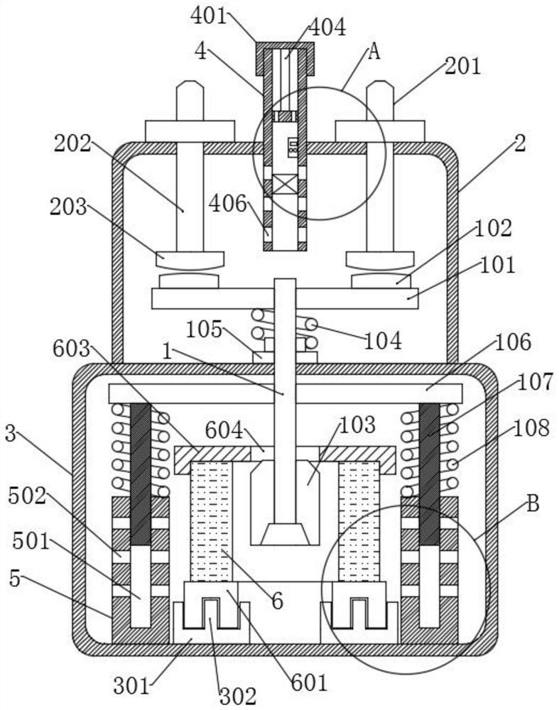
[0029] see Figure 1-3 As shown, the present invention is a driving device for a relay, including a push rod 1 and a moving iron core 103; a support plate 101 is fixedly installed on the top of the push rod 1; a pair of moving contacts 102 are fixed on the top of the support plate 101; the bottom of the support plate 101 A moving iron core 103 is provided; a support plate 106 is arranged laterally below the support plate 101 ; a pair of guide rods 107 are integrall...


PUM


Abstract

The invention discloses a driving device for a relay, and belongs to the technical field of relays. The device comprises a push rod and a movable iron core; a support plate is fixedly mounted at the top of the push rod; a pair of moving contacts is fixed at the top of the support plate; a movable iron core is arranged at the bottom of the support plate; a supporting plate is transversely arrangedbelow the support plate; a pair of guide rods is integrally formed at the bottom of the supporting plate. The invention further provides a relay. The relay comprises the driving device. The driving device can be matched with a cavity formed in an upper shell and a lower shell in an up-and-down moving manner; a heat dissipation pipeline is fixed to the top of the upper shell and extends into the upper shell; a positioning guide piece is fixed at the bottom of the lower shell; and a driving coil is arranged in the positioning guide piece. The driving device is movably matched with the upper shell and the lower shell; the heat dissipation pipeline is fixed to the top of the upper shell. After an existing relay is used for a period of time, a push rod is difficult to pull in and release, and heat is difficult to discharge in time. With the relay and the driving device adopted, the problems of the existing relay are solved.

Description

technical field [0001] The invention belongs to the technical field of relays, in particular to a driving device for a relay and a relay having the same. Background technique [0002] The power relay is a high-voltage and high-power power breaking device. The low-voltage coil flows through the current to generate electromagnetic force. The moving iron core drives the push rod to make the moving contact plate and the static contact contact. High-voltage connection, after the low-voltage coil is powered off, push The rod drives the movable contact plate to disconnect from the static contact under the reaction force of the reset elastic member, and through the frequent above-mentioned movement process, the frequent on-off control of the circuit is realized. The relay is widely used in electric vehicles, solar power generation, energy storage power generation, power distribution and power consumption fields. [0003] After the existing relay has been used for a period of time, ...

Claims


Application Information

Patent Timeline
Patent Type & Authority Applications(China)
IPC IPC(8): H01H50/64H01H50/12H01H50/04H01H50/02
CPCH01H50/64H01H50/12H01H50/041H01H50/02
Inventor 王兴生
Owner 阜阳中骄智能科技有限公司
Why Eureka
Try Eureka