Heat transfer elements

a catalyst/reactor system and heat transfer element technology, applied in chemical/physical processes, liquid hydrocarbon mixture production, chemical apparatus and processes, etc., can solve the problems of increasing reactor weight and cost, adding complexity, etc., and achieve high catalyst productivity, high catalyst productivity, and high throughput

Active Publication Date: 2022-07-28
EMERGING FUELS TECH
View PDF3 Cites 0 Cited by
  • Summary
  • Abstract
  • Description
  • Claims
  • Application Information

AI Technical Summary

Benefits of technology

[0013]It is desirable to operate the reactor of the present invention at high throughput and high catalyst productivity. Productivity relates to volumes of reactant gases converted per volume of catalyst per unit time. High catalyst productivity requires high capacity to remove the heat generated by the exothermic reaction. One approach to solve this problem has been to use small diameter reactor tubes which have a high ratio of surface area to catalyst volume. However, using small tubes requires a large number of tubes which adds complexity and increases reactor weight and cost. It is desirable to use large diameter tubes which make it easier to load catalyst while reducing reactor weight and cost. The heat transfer elements of the present invention make it possible to use larger tubes and operate at relatively high catalyst productivity compared to what would be possible without the heat transfer elements of the present invention. Heat transfer elements as described herein may increase the heat removal capacity measured as the overall heat transfer rate by a factor of two or three or more times what it would be for the same tube without these heat transfer elements. The heat transfer elements described herein with two or more legs that are substantially curved and at least two legs that have a foot to engage the inside wall of the tube can be installed with a moderate force as the curved legs have some flexibility to account for minor variations in the tube inside diameter and imperfect roundness. The heat transfer elements described herein are pressed into the tubes and make thermal contact by compression of the legs with no brazing, welding, gluing, or any other bonding method. The substantial curve of the legs also make it possible to adjust the outside dimensions of the heat transfer elements to customize the fit in the tubes and finally the heat transfer elements described herein can be any length but the preferred length is between three and fifty tube inside diameters to assure minimum drag as the heat transfer elements are pressed into the tube in sequential, end to end fashion filling the interior of the tube in the reaction zone which will be filled with catalyst, such catalyst filling the voids between the legs of the heat transfer elements and the tube inner wall.

Problems solved by technology

However, using small tubes requires a large number of tubes which adds complexity and increases reactor weight and cost.

Method used


Image

  • Heat transfer elements
  • Heat transfer elements
  • Heat transfer elements

Examples


Embodiment Construction

[0019]The devices and methods discussed herein are merely illustrative of specific manners in which to make and use this invention and are not to be interpreted as limiting in scope.

[0020]While the devices and methods have been described with a certain degree of particularity, it is to be noted that many modifications may be made in the details of the construction and the arrangement of the devices and components without departing from the spirit and scope of this disclosure. It is understood that the devices and methods are not limited to the embodiments set forth herein for purposes of exemplification.

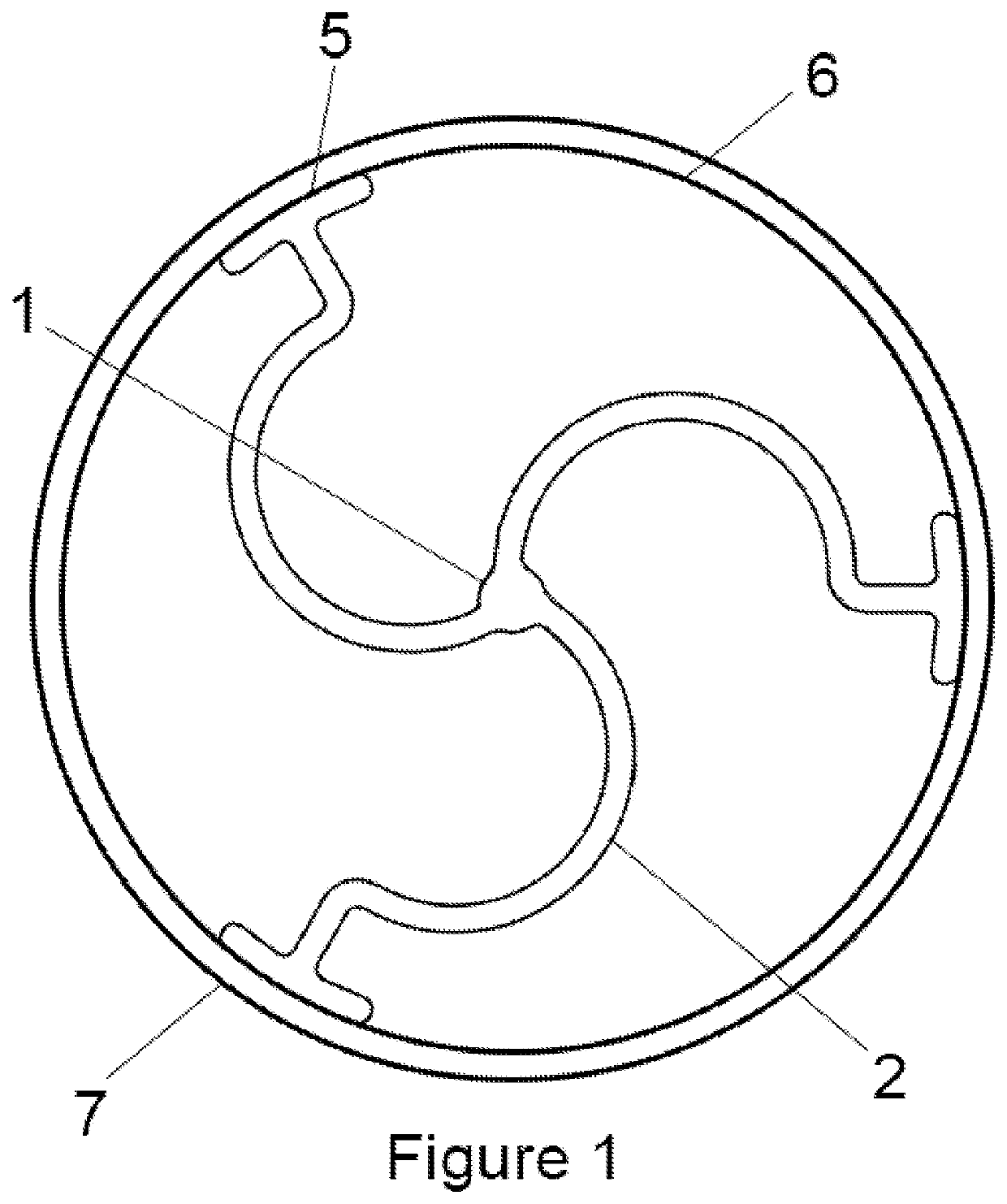
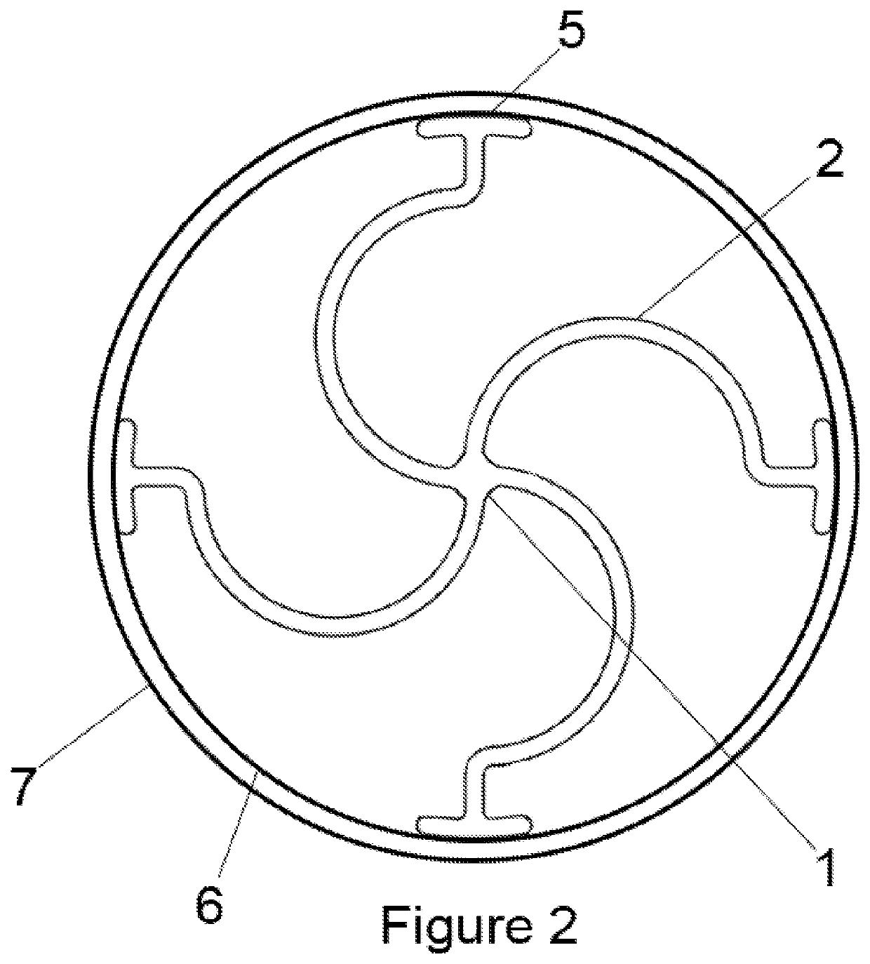
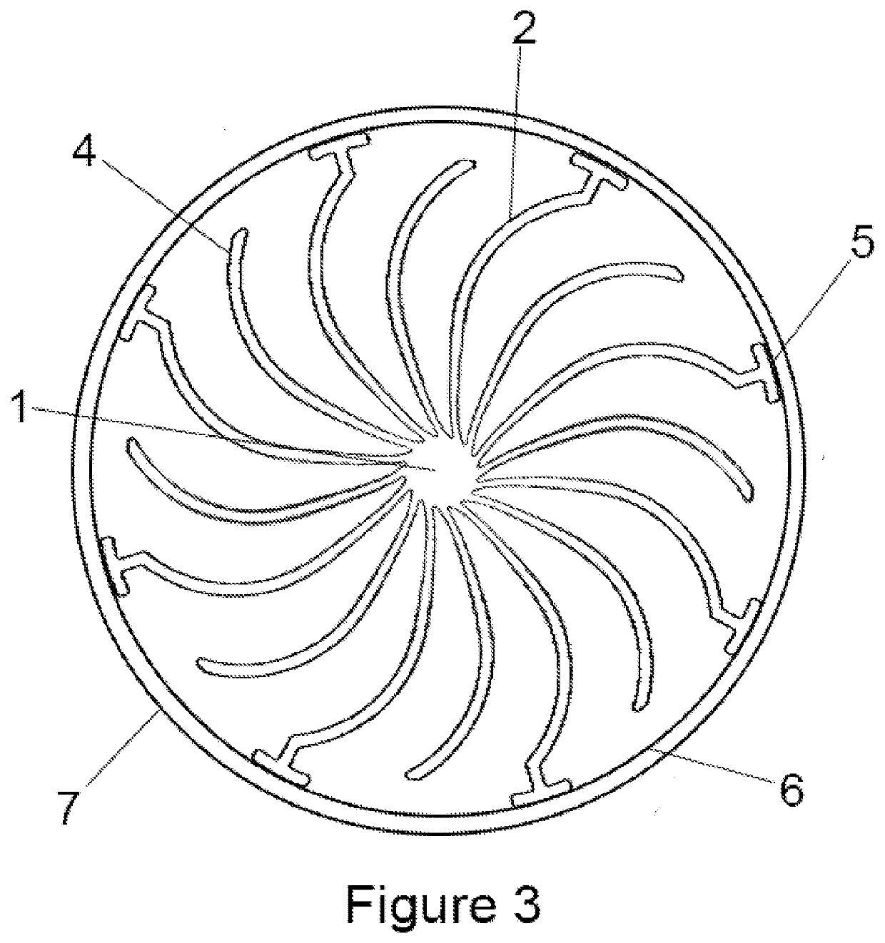
[0021]In general, in a first aspect, the invention relates to a heat transfer element 1 with substantially curved legs 2 to improve heat transfer in a vertical tubular fixed bed reactor 3. The heat transfer elements may have two or more legs 2 and any number of sub-legs 4 wherein at least two of the legs 2 have a foot 5 and make substantial contact with the inner wall 6 of the tubes ...


PUM


Abstract

A method for enhancing the heat transfer performance of a vertical tubular reactor by adding heat transfer elements inside the reactor tubes. Such heat transfer elements have two or more substantially curved legs of equal length with no cross fins, each with a foot that engages the inside wall of the tube, and can optionally have two or more substantially curved sub-legs that do not engage the wall of the tube.

Description

CROSS REFERENCE[0001]Not Applicable.BACKGROUND OF THE INVENTIONField of the Invention[0002]This invention relates generally to enhancing heat transfer in a catalyst / reactor system for exothermic catalytic reactions, particularly Fischer Tropsch and related reactions.Description of the Related Art[0003]Exothermic chemical reactions require excellent heat transfer to maintain the reaction within a targeted temperature range, especially in a commercial process unit, such as in chemical plants or petroleum refineries where great amounts of heat need to be transferred. An example of an exothermic chemical reaction is the Fischer Tropsch reaction. While many exothermic reactions may be conducted in the reactor of the present invention, the invention is described as a Fischer Tropsch reactor.[0004]Various processes are known for the conversion of carbonaceous feeds or light hydrocarbon containing gases into normally liquid products, such as methanol, higher alcohols, and hydrocarbon fuels ...

Claims


Application Information

Patent Timeline
Patent Type & Authority Applications(United States)
IPC IPC(8): B01J8/06
CPCB01J8/06B01J2208/00132B01J8/067B01J2208/00115B01J2208/00212B01J2208/00238B01J2208/065B01J2208/0084C10G2/34
Inventor AGEE, KENNETH L.
Owner EMERGING FUELS TECH
Why Eureka
Try Eureka