
Resource allocation method for front-end and rear-end cooperative communication in substation monitoring

A substation monitoring and resource allocation technology, which is applied in the resource allocation field of front-end and back-end collaborative communication in substation monitoring, can solve problems such as unreasonable allocation of communication resources and uneven utilization of workstation server computing resources.

Pending Publication Date: 2021-01-05
CSG EHV POWER TRANSMISSION
View PDF1 Cites 4 Cited by
  • Summary
  • Abstract
  • Description
  • Claims
  • Application Information

AI Technical Summary

Problems solved by technology

[0004] In order to solve the problems of unreasonable allocation of communication resources and uneven utilization of computing resources of workstation servers in the process of data transmission between front-end monitoring nodes and back-end workstations of substations, the present invention proposes a resource allocation method for front-end and back-end collaborative communication in substation monitoring. Make the resources in the substation wireless communication network be allocated reasonably, reduce the delay in the data transmission process, and improve the energy efficiency of the substation monitoring node

Method used


Image

  • Resource allocation method for front-end and rear-end cooperative communication in substation monitoring
  • Resource allocation method for front-end and rear-end cooperative communication in substation monitoring
  • Resource allocation method for front-end and rear-end cooperative communication in substation monitoring

Examples


Embodiment 1

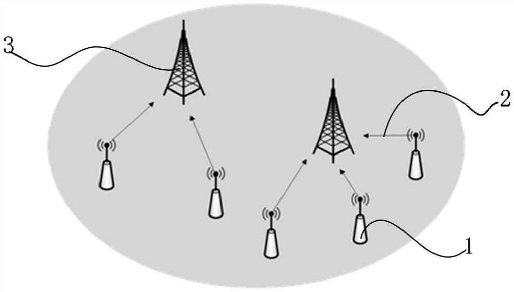
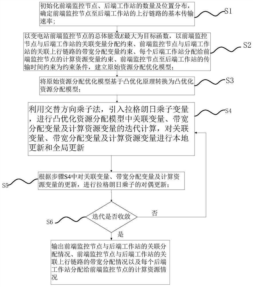
[0067] Such as figure 1 The system structure diagram of the front-end and back-end collaborative communication in the substation monitoring is shown, figure 1 Among them, 1 indicates the front-end monitoring node, 2 indicates the uplink from the front-end monitoring node to the back-end workstation, and 3 indicates the back-end workstation. The front-end monitoring node 1 of the substation transmits data to the back-end workstation 3 through the uplink 2. In the process of transmitting data with the back-end workstation 3, problems such as unreasonable allocation of communication resources and uneven utilization of computing resources of workstation servers may occur, such as figure 2 Shown is a schematic flowchart of a resource allocation method for front-end and back-end collaborative communication in substation monitoring proposed by the present invention, and the method includes:

[0068] S1. Initialize the number and location distribution of front-end monitoring nodes a...


PUM


Abstract

The invention provides a resource allocation method for front-end and rear-end cooperative communication in transformer substation monitoring, and solves the problems of unreasonable communication resource allocation and non-uniform calculation resource utilization during front-end and rear-end data transmission. The method comprises the steps of: taking the maximum overall energy efficiency of atransformer substation front-end monitoring node as an objective function; establishing an original resource allocation optimization model by taking the association variable allocation constraint, thebandwidth allocation variable constraint of the association uplink, the computing resource variable constraint allocated to the front-end monitoring node by each rear-end workstation and the transmission delay constraint as constraint conditions, and converting the original resource allocation optimization model into a convex optimization resource allocation model by utilizing a convex optimization principle; and performing local updating and global updating to form a problem form which can be solved by an alternating direction multiplier method, so that the calculation complexity is reduced,the energy efficiency of front-end and rear-end cooperative communication in substation monitoring is optimized, the requirement of substation monitoring on transmission delay is met, and a guaranteeis provided for real-time monitoring. And thus, communication and computing resources in the wireless network are reasonably utilized.

Description

technical field [0001] The invention relates to the technical field of substation wireless communication transmission, and more specifically, to a resource allocation method for front-end and back-end collaborative communication in substation monitoring. Background technique [0002] In recent years, with the development of society and economy, the scale of power consumption of users has been continuously expanding, and the demand for electric energy has increased. Substations play an important role in the process of power transmission. At the level of monitoring, it also puts forward higher requirements for the power grid itself. [0003] At present, for substation monitoring, most of the solutions are to upload the collected monitoring video or image information to the server for analysis, but the large amount of video image transmission and little effective information will occupy and waste a lot of network bandwidth resources. Considering the cost, such solutions will r...

Claims


Application Information

Patent Timeline
IPC IPC(8): H04W16/10H04W28/06H04W28/20H04W72/04H04W72/12
CPCH04W16/10H04W72/04H04W72/12H04W28/20H04W28/06Y02D30/70
Inventor 田霖林睿陆国生陈保豪朱一峰刘淼茹正辉
Owner CSG EHV POWER TRANSMISSION
Learn More