Stamping equipment

A technology of stamping equipment and equipment, used in metal processing equipment, metal processing, manufacturing tools, etc., can solve the problems of insufficient stamping, inability to judge stamping parts in place, and difficult to judge materials.

Pending Publication Date: 2021-01-08
韩光明
View PDF6 Cites 0 Cited by
  • Summary
  • Abstract
  • Description
  • Claims
  • Application Information

AI Technical Summary

Problems solved by technology

[0003] In the stamping process, there may be situations where the stamping is not in place. In existing life, whether the stamping is in place is judged by observing the shape of the stamping part with the naked eye, or with the help of measuring tools. However, these judgments are usually in all The inspection will only be carried out after all the stamping parts are stamped, and it is impossible to make a preliminary judgment on whether the stamping parts are stamped in place immediately, and if the existing stamping parts have similar appearance, it is difficult to judge the material

Method used


Image

  • Stamping equipment
  • Stamping equipment
  • Stamping equipment

Examples


Embodiment 1

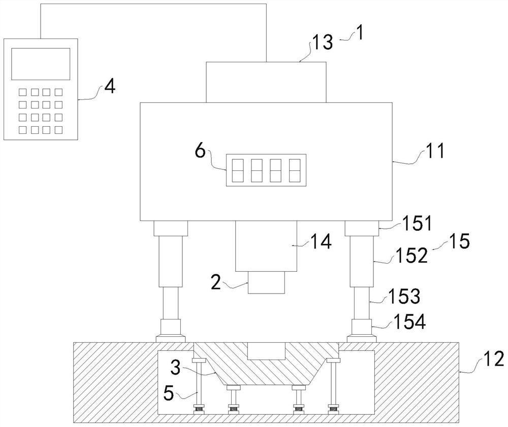
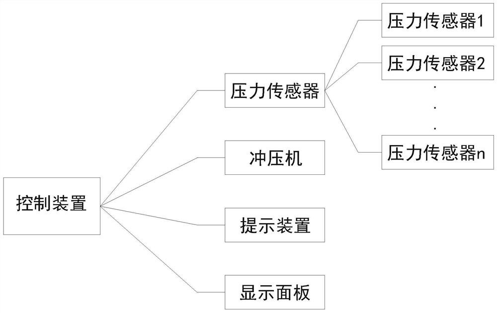
[0037] see Figure 1-4 , a stamping equipment, including equipment body 1, stamping die 2, stamping die base 3 and computer control device 4; stamping die 2 and stamping die base 3 are installed on the equipment body 1, and distributed up and down; computer control device 4 and The device body 1 is connected to control the stamping die 2 to move down and stamp the workpiece placed on the stamping die base 3; more than one pressure sensor 5 is arranged at the bottom of the stamping die base 3, and the number of more than one pressure sensor 5 forms a shape that matches the mold , the upper end surface of the pressure sensor 5 is in contact with the outer surface of the stamping die base 3; the pressure sensor 5 is connected with the computer control device 4, and the computer control device 4 is preset with a pressure qualified range; when the stamping die 2 is controlled by the computer control device 4 to punch When the workpiece in the die base 3 is stamped, the pressure sen...


PUM


Abstract

The invention discloses stamping equipment, and belongs to the field of machining. The stamping equipment comprises an equipment body, a stamping die, a stamping die holder and a computer control device; the stamping die and the stamping die holder are both installed on the equipment body and are distributed up and down; the computer control device is connected with the equipment body and can control the stamping die to move downwards to stamp a workpiece placed on the stamping die holder; more than one pressure sensor is arranged at the bottom of the stamping die holder, and the upper end surfaces of the pressure sensors make contact with the outer surface of the stamping die holder; the pressure sensors are connected with the computer control device; and a pressure qualified range is preset in the computer control device. According to the stamping equipment, the multiple pressure sensors are used for monitoring the pressure, sensed in the stamping process, of all points to judge whether the stamped piece is stamped in place, when the stamped piece is not stamped in place, the situation can be found in time, and the stamped piece can be stamped again; and meanwhile, the stamping die and the stamping die holder are electrically connected with the outside, the workpiece can be powered on in the stamping process to obtain a resistance value, and thus the material of the workpiececan be judged.

Description

technical field [0001] The invention relates to the field of mechanical processing, more specifically, to a punching equipment. Background technique [0002] Stamping processing is a production technology that uses the power of conventional or special stamping equipment to directly subject the sheet to deformation force and deform in the mold, so as to obtain product parts of a certain shape, size and performance. Sheet metal, mold and equipment are the three elements of stamping processing. The mold used for stamping is called stamping die, or punching die for short. Die is a special tool for mass processing materials (metal or non-metal) into required punching parts. Dies are very important in stamping. Without qualified dies, mass stamping production will be difficult; without advanced dies, advanced stamping technology will not be realized. The stamping process, dies, stamping equipment and stamping materials constitute the three elements of stamping processing. Only ...

Claims


Application Information

Patent Timeline
IPC IPC(8): B21D22/02B21C51/00
CPCB21D22/02B21C51/00
Inventor 韩光明
Owner 韩光明
Why Eureka
Try Eureka