Pop-top can pull ring forming equipment

A technology for forming equipment and cans, which is applied to metal processing equipment, feeding devices, positioning devices, etc., to achieve the effect of rapid stamping

Inactive Publication Date: 2021-01-08
杨治宇
View PDF0 Cites 1 Cited by
  • Summary
  • Abstract
  • Description
  • Claims
  • Application Information

AI Technical Summary

Problems solved by technology

[0005] In order to overcome the shortcoming of manually holding the iron sheet on the stamping mechanism for stamping, thereby prolonging the stamping process, the technical problem of the present invention is to provide a method for stamping iron sheets without manually holding the iron sheet, and can quickly press the iron sheet. Ring-pull forming equipment for sheet punching

Method used


Image

  • Pop-top can pull ring forming equipment
  • Pop-top can pull ring forming equipment
  • Pop-top can pull ring forming equipment

Examples


Embodiment 1

[0024] A kind of pull ring forming equipment for pop cans, such as figure 1 As shown, it includes a base 1, a support base 2, a servo motor 3, a stamping mechanism 4, a propulsion mechanism 5, a rotating mechanism 6 and an extrusion mechanism 7. There is a servo motor 3, the upper right side of the base 1 is provided with a stamping mechanism 4, the upper part of the base 1 is provided with a propulsion mechanism 5, the propulsion mechanism 5 is provided with a rotating mechanism 6, and the stamping mechanism 4 is provided with an extrusion mechanism 7.

[0025] When the user needs to make the pull ring of the pop can, this device can be used. First, the iron sheet to be made of the pull ring is placed on the propulsion mechanism 5, and then the servo motor 3 is turned on, and the servo motor 3 drives the propulsion mechanism 5 to move to the right, and the The iron sheet moves to the bottom of the stamping mechanism 4, and a part of the iron sheet is stamped by the stamping m...

Embodiment 2

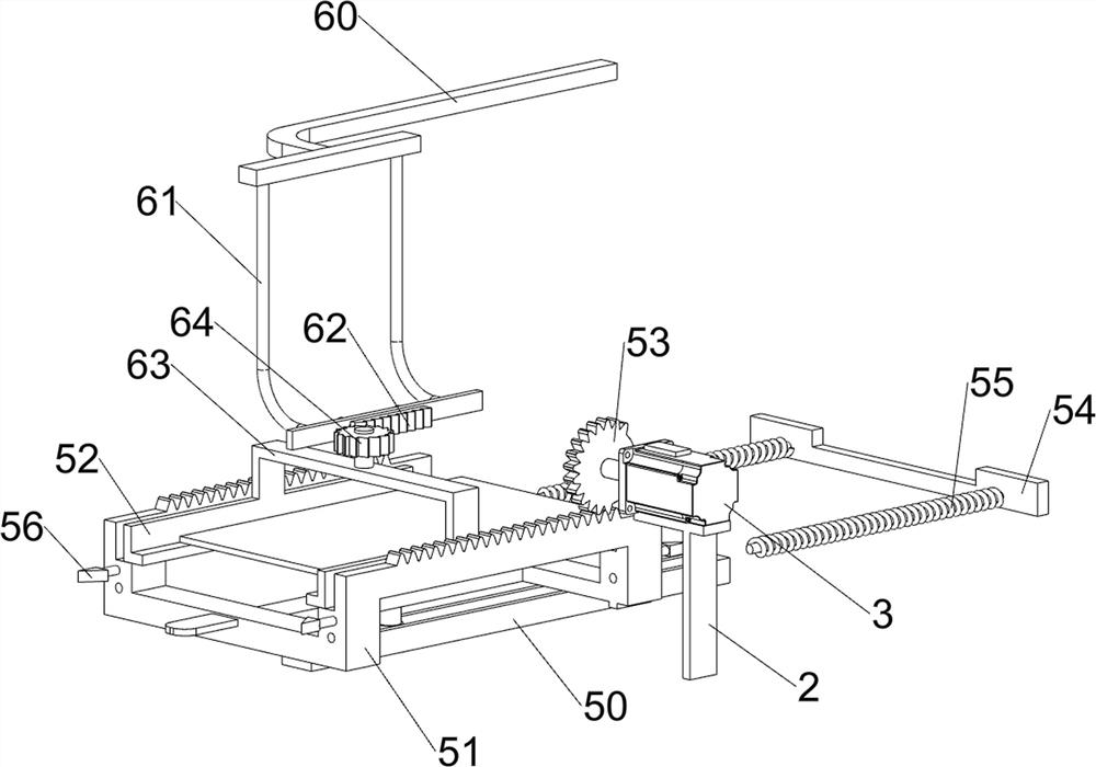
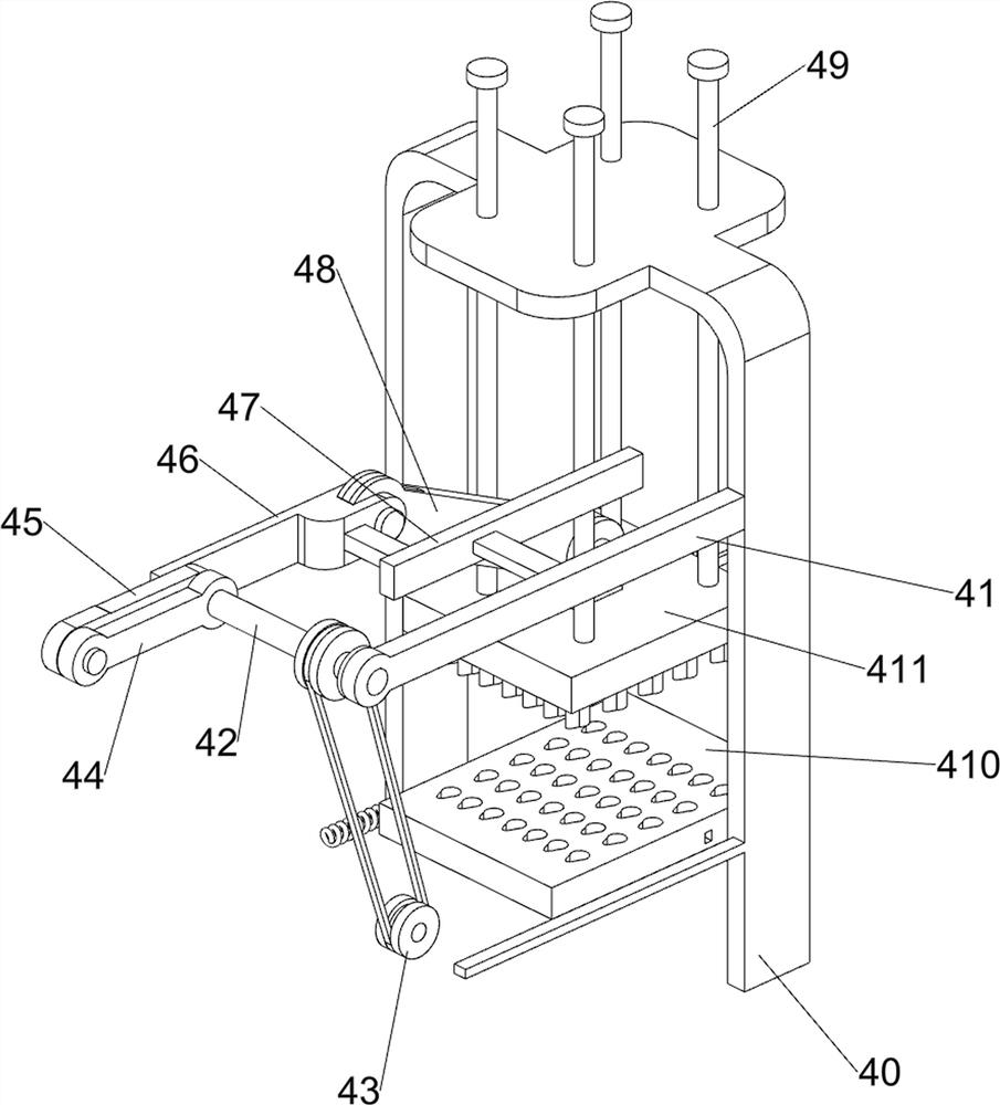
[0027] On the basis of Example 1, such as figure 2 , image 3 , Figure 4 with Figure 5 As shown, the stamping mechanism 4 includes a first fixed frame 40, a first bearing seat 41, a first rotating shaft 42, a transmission assembly 43, a first rotating handle 44, a second rotating handle 45, a connecting rod 46, and a first slide rail 47 , rotating rod 48, slide bar 49, stamping plate 410 and lower pressing plate 411, base 1 upper right side is provided with first fixed mount 40, and first fixed mount 40 is connected with support base 2, and first fixed mount 40 front side left side A first bearing seat 41 is provided, and a first rotating shaft 42 is rotatably arranged on the first bearing seat 41. A transmission assembly 43 is connected between the first rotating shaft 42 and the output shaft of the servo motor 3. The rear side of the first rotating shaft 42 is provided with The first rotating handle 44, the first rotating handle 44 is provided with a second rotating ha...

Embodiment 3

[0036] On the basis of Example 2, such as Image 6 As shown, it also includes a third bearing seat 8, a second rotating shaft 9, a slide plate 10 and a torsion spring 11. The left side of the upper part of the base 1 is symmetrically provided with a third bearing seat 8. Between the third bearing seats 8 on both sides The rotary type is provided with a second rotating shaft 9 , a slide plate 10 is arranged on the second rotating shaft 9 , a torsion spring 11 is arranged on the second rotating shaft 9 , and the torsion spring 11 is connected with the third bearing seat 8 .

[0037] After the special-shaped rack 51 moves to the left and rotates half a circle, since the side of the special-shaped rack 51 is provided with a bump, the bump contacts the slide plate 10. In the initial state, the slide plate 10 is in a vertical state, and the bump moves to the left. And promote the bottom of slide plate 10, make the top of slide plate 10 turn to the right, at this moment, torsion spri...


PUM


Abstract

The invention relates to forming equipment, in particular to pop-top can pull ring forming equipment. According to the pop-top can pull ring forming equipment, an iron sheet does not need to be manually held by hand when being stamped, and the iron sheet can be rapidly stamped. The pop-top can pull ring forming equipment comprises a base used for installing the whole equipment, a supporting seat arranged in the middle of one side of the upper part of the base; a servo motor arranged at the upper part of the supporting seat; and a stamping mechanism arranged on one side of the upper part of thebase. According to the pop-top can pull ring forming equipment provided by the invention, the effects that the iron sheet does not need to be manually held by hand when being stamped, and the iron sheet can be rapidly stamped are achieved; and an iron sheet needing to be stamped is placed on fixing blocks on the two sides, and then the iron sheet is moved to the position below a lower pressing plate through the pushing mechanism so as to be stamped, so that the iron sheet does not need to be manually held by hand.

Description

technical field [0001] The invention relates to a forming device, in particular to a forming device for a pull ring of a can. Background technique [0002] Pop-top cans are processed through aluminum materials, and then processed into can bodies and can lids through its materials. At the same time, there is a pull ring on the top of the can lid, so that consumers can open the lid of the pop-top can by pulling the pull ring, so that users Liquids from cans can be used. [0003] In the process of making the pull ring of the can, people usually place the iron sheet under the stamping mechanism, and wait for the stamping mechanism to stamp the iron sheet. After the stamping is completed, the worker places the other side of the iron sheet under the stamping mechanism. The stamping mechanism can stamp the other side of the iron sheet. After the stamping is completed, the stamped iron sheet is removed, and then a new iron sheet to be replaced is replaced to continue stamping the i...

Claims


Application Information

Patent Timeline
Patent Type & Authority Applications(China)
IPC IPC(8): B21D51/26B21D43/00B21D43/04
CPCB21D43/003B21D43/04B21D51/26B21D51/2692
Inventor 杨治宇
Owner 杨治宇
Why Eureka
Try Eureka