Steel bar cutting device for building field
A cutting device and technology in the field, which is applied in the field of construction equipment and construction, can solve the problems of long time consumption, low cutting efficiency of the device, and low practicability.
- Summary
- Abstract
- Description
- Claims
- Application Information
AI Technical Summary
Problems solved by technology
Method used
Image
Examples
Embodiment 1
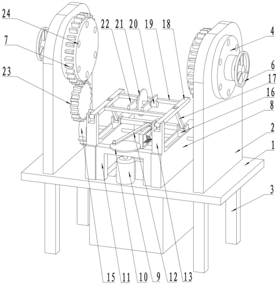
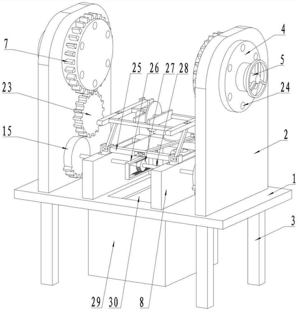
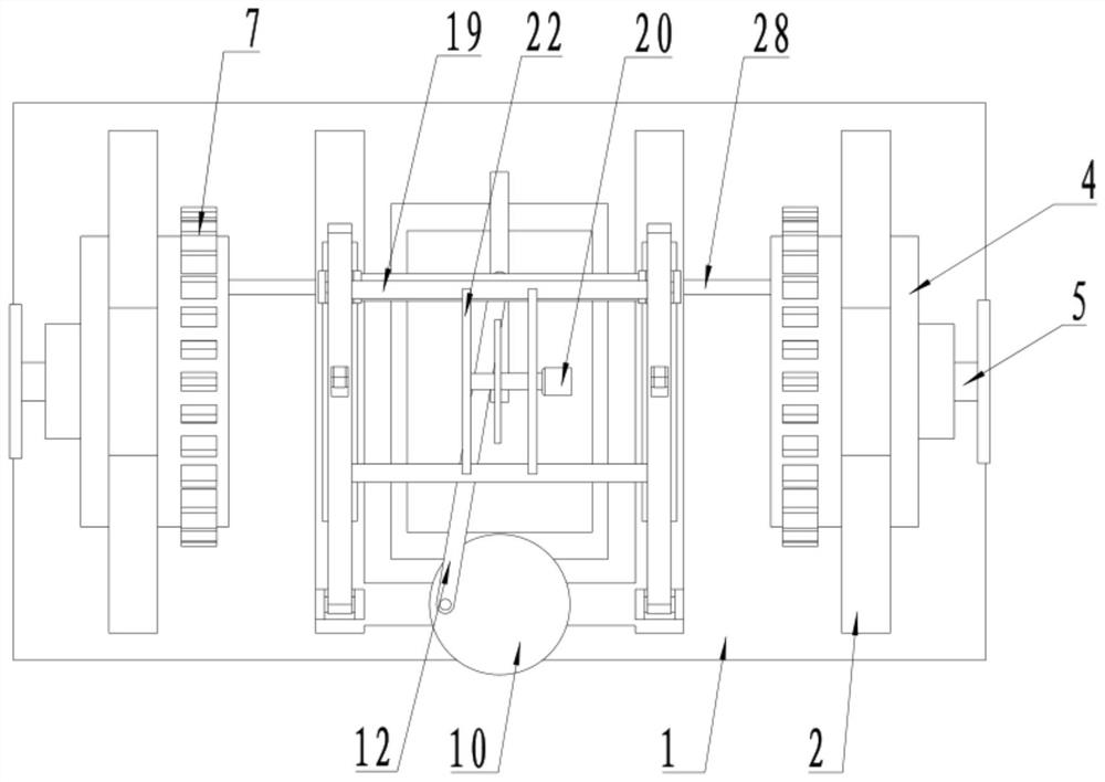
[0022] see Figure 1-4 , a steel bar cutting device for the construction field, comprising a bottom plate 1, four corners of the bottom of the bottom plate 1 are fixedly connected to support legs 3, both sides of the bottom plate 1 are fixedly connected to a mounting plate 2, and the upper end of the mounting plate 2 is rotatably connected to a feeding column 4, A clamping hole 24 is provided on the feeding column 4, and the transmission gear ring 7 is fixedly connected to the feeding column 4 on one side of the installation plate 2, and the transmission gear 23 is connected to the side of the installation plate 2 below the transmission gear ring 7, and the transmission gear 23 passes through The transmission gear ring 7 is connected to the feeding column 4 by transmission, the bottom plate 1 between the installation plates 2 is fixedly connected to the support plate 8, the upper side of the support plate 8 is fixedly connected to the support column 13, and the top of the suppo...
Embodiment 2
[0029] see Figure 1-4 The other content of this embodiment is the same as that of Embodiment 1, except that: a discharge port 30 is provided on the bottom plate 1 between the support plates 8, and the bottom of the bottom plate 1 below the discharge port 30 is fixedly connected to the waste bin 29.
[0030]During the implementation of the present invention, place the two ends of the steel bar with cutting in the clamping hole 24, turn the adjustment handle 6 to drive the adjustment column 5 to rotate, and the arc-shaped adjustment block 31 on the adjustment column 5 rotates to squeeze the movable column 38 pulley 40, so that the positioning block 39 at one end of the movable column 38 clamps and fixes the two ends of the steel bar, then starts the drive motor 9, and drives the connecting rod 25 to slide under the action of the second transmission rod 12 on the transmission wheel 10, and the connecting rod 25 drives the sliding block 16 to move to one side, the sliding block 1...
PUM
 Abstract
Description
Claims
Application Information
 - R&D Engineer
- R&D Manager
- IP Professional
- Industry Leading Data Capabilities
- Powerful AI technology
- Patent DNA Extraction
Browse by: Latest US Patents, China's latest patents, Technical Efficacy Thesaurus, Application Domain, Technology Topic, Popular Technical Reports.
© 2024 PatSnap. All rights reserved.Legal|Privacy policy|Modern Slavery Act Transparency Statement|Sitemap|About US| Contact US: help@patsnap.com


