
Stainless steel tableware polishing device

A technology for stainless steel and tableware, which is applied in the direction of grinding machines, manufacturing tools, and surface polishing machine tools. It can solve the problems of reduced work efficiency, inability to grind, and omission of corners and corners, so as to improve the work efficiency of grinding, and the installation is simple and fast. The effect of easy operation

Active Publication Date: 2021-01-08
揭阳市东拓家居实业有限公司
View PDF6 Cites 1 Cited by
  • Summary
  • Abstract
  • Description
  • Claims
  • Application Information

AI Technical Summary

Problems solved by technology

[0004] The purpose of the present invention is to provide a kind of stainless steel tableware grinding device, to solve the traditional grinding proposed in the above-mentioned background technology is exactly to adopt the grinding machine to carry out the grinding work slowly bit by bit along the outer surface of stainless steel tableware, because tableware The different specifications and sizes of the tableware, and the non-uniformity of the shape make it possible to miss or fail to polish the edges and corners during grinding, which will cause harm to the user when it is used later, and does not meet the acceptance criteria for tableware. , and grinding one by one greatly increases the workload and greatly reduces the work efficiency, which cannot meet the needs of the current enterprises for efficient production.

Method used


Image

  • Stainless steel tableware polishing device
  • Stainless steel tableware polishing device
  • Stainless steel tableware polishing device

Examples


Embodiment Construction

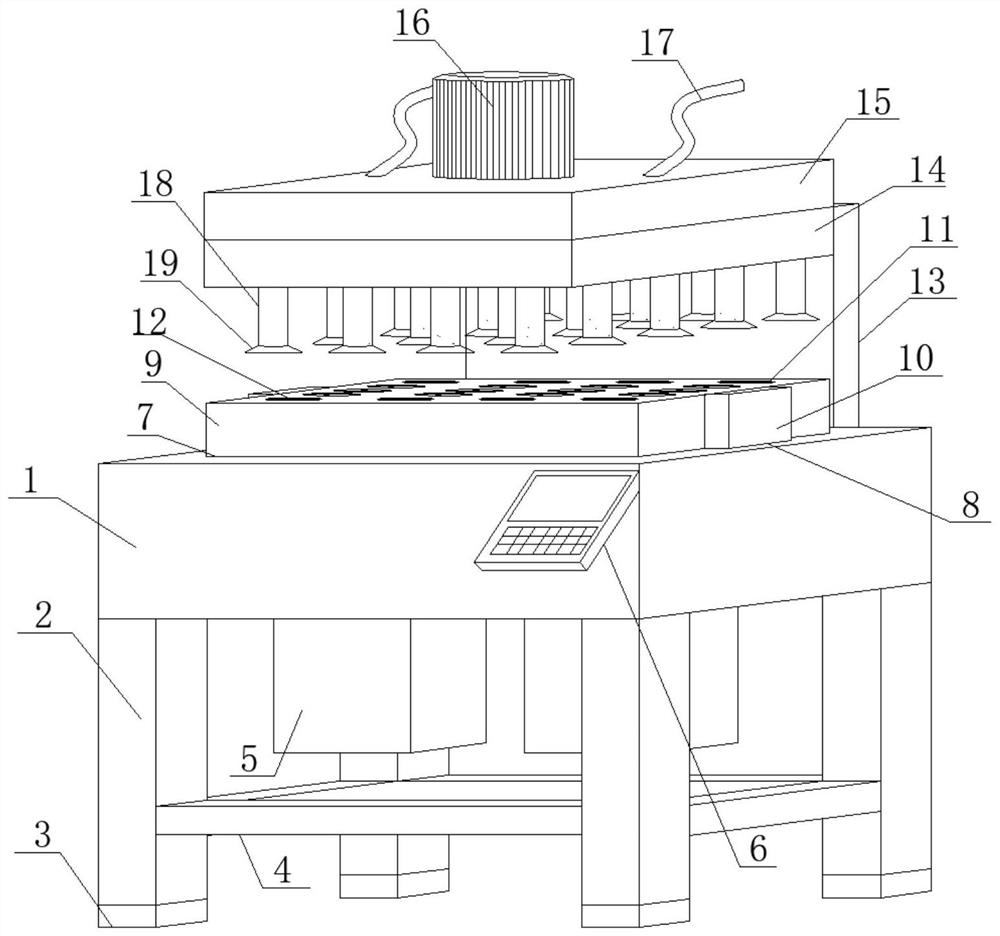
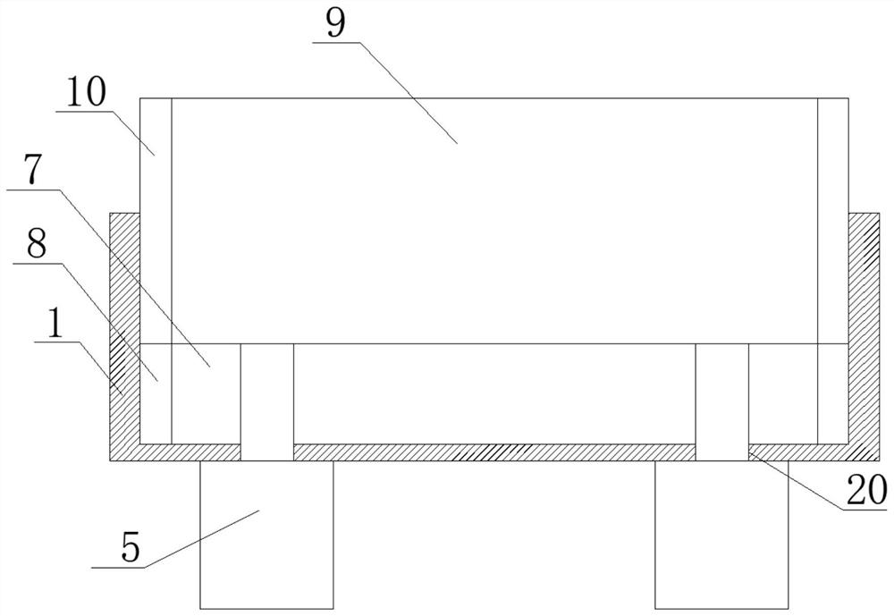
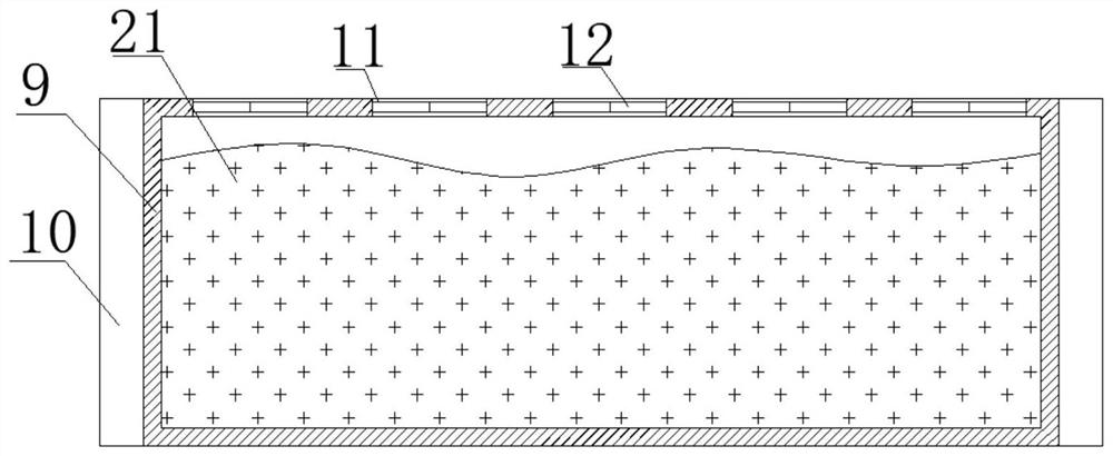
[0027]SeeFigure 1-3 In the embodiment of the present invention, a stainless steel tableware polishing device includes a fixed box body 1. The bottom surface of the fixed box body 1 is welded with a support pole 2 vertically downward, and the bottom end of the support pole 2 is fixedly clamped with a primer The cushion block 3, the side of the support pole 2 is horizontally welded with a fixed cross bar 4, the number of the support pole 2 is four, and the four support poles 2 are arranged parallel to each other, and the four support poles 2 are respectively It is fixedly arranged on the bottom surface of the fixed box 1 near the four corners. The number of bottom rubber pads 3 is consistent with the number of support poles 2 and is set in one-to-one correspondence. The bottom rubber pads 3 are made of soft rubber materials. The fixed crossbar 4 is in the shape of a lip and is fixed horizontally head and tail between the four support rods 2 on the side near the bottom end. The bottom ...


PUM


Abstract

The invention discloses a stainless steel tableware polishing device, and relates to the field of tableware polishing. The stainless steel tableware polishing device comprises a fixed box body, wherein a supporting vertical rod is vertically welded downwards on the bottom surface of the fixed box body; a bottom rubber cushion block is fixedly clamped at the bottom end of the supporting vertical rod; a fixed cross rod is horizontally welded on the side edge of the supporting vertical rod; a bottom air cylinder is connected to the bottom surface of the fixed box body through a vertical bolt; a control panel is obliquely welded on one side edge of the fixed box body; a movable groove is horizontally formed in the top surface of the fixed box body; limiting grooves are vertically and symmetrically formed in the two side edges of the movable groove; a processing box body is clamped on the inner side edge of the movable groove; and limiting parts are vertically and symmetrically welded on the two side edges of the processing box body. The stainless steel tableware polishing device is simple in design integrated structure and convenient to operate, the surface of tableware is polished inan all-around and dead-angle-free mode by adopting a sand grain polishing mode, the stainless steel tableware polishing device is more reasonable and efficient, meanwhile, the batch polishing effect can be achieved, and the polishing working efficiency is greatly improved.

Description

Technical field[0001]The invention relates to the technical field of tableware polishing, in particular to a stainless steel tableware polishing device.Background technique[0002]With the progress and development of society, people pay more and more attention to the concept of systematization of their living environment. First of all, in the room design, through a unified design, all kinds of living appliances are closely connected with each other, and a tacit understanding is reached. Uniform furniture, wall and floor decorations, fabrics, lamps, and overall colors reflect each other, and more and more people are turning their attention to more subtle places, such as choosing a set of tableware that suits their home atmosphere. The style of the restaurant should complement the design of the restaurant; the taste and lifestyle. A set of tableware with beautiful forms and sophisticated craftsmanship can also adjust people's mood when eating and increase appetite.[0003]For the variety ...

Claims


Application Information

Patent Timeline
IPC IPC(8): B24B31/10B24B31/12
CPCB24B31/10B24B31/12
Inventor 徐美玲
Owner 揭阳市东拓家居实业有限公司
Learn More