Printed bag punching die

A printing bag and punching technology, which is applied in metal processing and other directions, can solve the problems of poor punching effect of printing bags, achieve the effect of improving processing efficiency, improving precision and quality, and avoiding moving damage

Active Publication Date: 2021-01-08
宁波甜宝生物信息技术有限公司
View PDF5 Cites 0 Cited by
  • Summary
  • Abstract
  • Description
  • Claims
  • Application Information

AI Technical Summary

Problems solved by technology

[0004] The purpose of the present invention is to solve the problem of poor punching

Method used


Image

  • Printed bag punching die
  • Printed bag punching die
  • Printed bag punching die

Examples


Embodiment

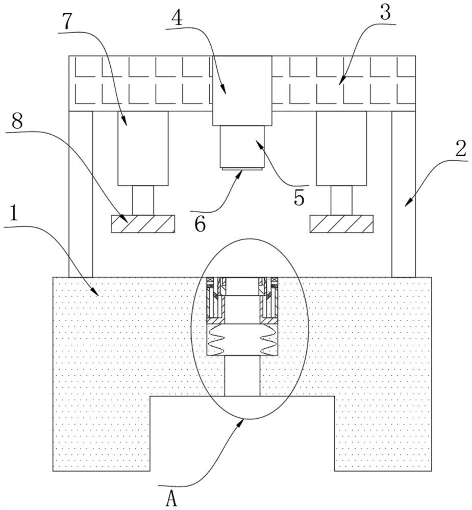
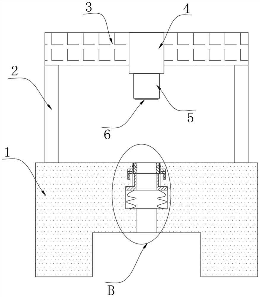
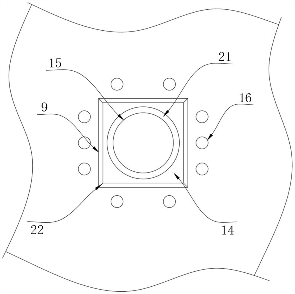
[0021] refer to Figure 1-5 , a printing bag punching die, comprising a lower die 1, the upper end of the lower die 1 is connected with a support plate 3 through a plurality of brackets 2, the bottom of the support plate 3 is fixed with a cylinder 4, and the bottom of the cylinder 4 is fixed with a punch 5, The bottom of the punch 5 is fixed with a pre-plate 6, the bottom of the support plate 3 is fixed with two symmetrically arranged push rods 7, the bottom of the two push rods 7 are fixed with a pressure plate 8, and the upper end of the lower die 1 is provided with a punching hole 9 The side wall of the punching hole 9 is provided with an expansion groove 10, and the bottom of the expansion groove 10 is provided with a blanking groove 11. The bottom of the expansion groove 10 is connected with a connecting sleeve 13 through a plurality of buffer springs 12, and the coefficient of stiffness of the buffer spring 12 is relatively high. The upper end of the connecting sleeve 13...


PUM


Abstract

The invention discloses a printed bag punching die which comprises a lower die. The upper end of the lower die is connected with a supporting plate through a plurality of supports, an air cylinder isfixed to the bottom of the supporting plate, a punch is fixed to the bottom of the air cylinder, a preset plate is fixed to the bottom of the punch, and two push rods which are symmetrically arrangedare fixed to the bottom of the supporting plate. Press plates are fixed to the bottoms of the two push rods correspondingly, a punching hole is formed in the upper end of the lower die, an expanding groove is formed in the side wall of the punching hole, and a discharging groove is formed in the bottom of the expanding groove in a penetrating mode. The printed bag punching die has the advantages that push plates are pushed through the push rods, a printed bag can be tightly pressed by the push plates to be in a tightened stable state, and therefore the stability and the effectiveness of the punching process are guaranteed; and the preset plate is arranged and can make contact with piezoelectric ceramic firstly in the downward movement process of the punch, and therefore electrorheologicalfluid can be solidified and expanded to push cutting edges to move upwards, the printed bag at the punching position can be jacked up, and the punch can cooperate with the cutting edges to better accomplish the punching motion.

Description

technical field [0001] The invention relates to the technical field of printing bag processing, in particular to a punching die for a printing bag. Background technique [0002] Due to its excellent bearing and marking capacity, printed bags are suitable for various fields, and in many occasions, it is necessary to punch holes for printed bags to facilitate the extraction of printed bags, so the punching mold for printed bags emerges as the times require; [0003] When the existing printing bag punching mold is in use, there will still be a gap between the printing bag and the mold after the printing bag is tightened, so that the air in the gap will move during the punching process, so that the position of the printing bag punching process is easy to change. Inaccurate punching or pulling damage is caused. The existing mold cannot directly clean and collect the fragments after punching, which requires manual processing, causing more inconvenience. Contents of the invention...

Claims


Application Information

Patent Timeline
IPC IPC(8): B26F1/44B26D7/02B26D7/01B26D7/18
CPCB26F1/44B26D7/025B26D7/018B26D7/1854
Inventor 付金金
Owner 宁波甜宝生物信息技术有限公司
Why Eureka
Try Eureka