An automatic power cable unwinding device and its operating method

A power cable and automatic technology, applied in the field of electric power, can solve the problems of inaccurate braking force control, bending resistance, large motion inertia, damage, etc. of the cable disc, so as to avoid the problem of braking stability and high braking precision , the effect of improving the versatility

Active Publication Date: 2022-05-17
贵州电网有限责任公司都匀福泉供电局
View PDF12 Cites 0 Cited by
  • Summary
  • Abstract
  • Description
  • Claims
  • Application Information

AI Technical Summary

Problems solved by technology

However, during the cable unwinding process, due to the characteristics of the cable itself, such as bending resistance and large motion inertia, the cable reel will have uneven speed when rotating, loose coils, and cable dragging friction. As a result, the outer sheath or wire of the cable is worn out. If it is light, the cable needs to be repaired, and if it is serious, the entire cable needs to be replaced.
In view of the above situation, the prior art once proposed a manual braking method, that is, during the process of unwinding the cable reel, two staff members respectively take a wooden stick or an iron rod to touch the edge of the cable reel, thereby Realize the frictional braking of the cable reel and avoid the excessive speed of the cable reel. This operation method has the disadvantages of small safety factor, difficult braking and high labor cost.
[0003] In addition, some new braking methods have been proposed in the prior art, such as mechanical friction brakes. The principle is still to achieve braking of the cable reel by rubbing the edge of the cable reel. However, due to the specifications of the cable reel ( That is, the size) is different, which will cause the friction braking effect of the mechanical friction braking structure to be unstable when facing cable reels of different specifications
In addition, due to the long-term use of the cable reel, the edge of the cable reel will not be completely circular, and the surface of the edge of the cable reel will also have local unevenness. Therefore, the edge of the cable reel Friction braking will affect the smoothness of braking, and the braking effect is not ideal. In addition, the mechanical friction braking in the prior art also has defects such as inaccurate control of the braking force of the cable reel.
In addition, long-term friction on the edge of the cable reel may easily cause the edge of the cable reel to become thinner or even damaged.

Method used


Image

  • An automatic power cable unwinding device and its operating method
  • An automatic power cable unwinding device and its operating method
  • An automatic power cable unwinding device and its operating method

Examples


Embodiment 2

[0185] Embodiment 2 describes an operation method of an automatic power cable unwinding device. Wherein, the automatic power cable unwinding device adopts the power cable automatic unwinding device in the first embodiment above.

[0186] Utilize this operation method, can realize the automatic unwinding operation of cable reel 20, concrete operation process is as follows:

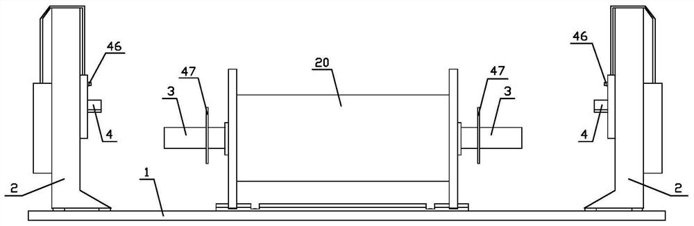
[0187] a. Align the flanges of the two intermediate transfer parts 3 with the middle holes of the cable reel 20, and fasten them with bolts. After the fastening is completed, the intermediate transfer parts 3 are connected to the cable reel 20 as one, as Figure 14 shown.

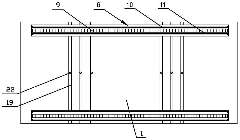
[0188] b. From the front side or rear side of the installation base plate 1, push the cable reel 20 with the intermediate transfer part 3 into a certain group of cable reel guide grooves 19, the group of cable reel guide grooves 19 and the cable The discs 20 are equal in width.

[0189] Wherein, the width of the cable reel 20 is the ...


PUM


Abstract

The invention discloses an automatic power cable unwinding device and an operation method thereof. Among them, the power cable automatic unwinding device includes an installation base plate, a door-shaped stand, a door-shaped stand walking mechanism, an intermediate transfer part, a lifting mechanism, a supporting part, a braking mechanism, a sensing part and a control part. The door-type stand is installed on the installation base plate, and is equipped with a door-type stand walking mechanism. Under the action of the door-shaped stand walking mechanism, the door-shaped stand can move left and right, the intermediate transfer part is used to connect with the cable reel to improve the versatility of the device of the present invention, and the lifting mechanism is used to drive the cable reel to lift When reaching a certain height, the braking mechanism cooperates with the sensing parts, etc., which is beneficial to realize unwinding the cable at a uniform speed. Since the present invention does not directly brake the cable reel, it avoids damage to the edge of the cable reel, and at the same time ensures the smoothness of braking. In addition, the braking precision of the device of the present invention is high.

Description

technical field [0001] The invention belongs to the technical field of electric power, and in particular relates to an automatic power cable unwinding device and an operation method thereof. Background technique [0002] At present, the power cables are all wound on the cable reel. When it is necessary to unwind the cable, the cable reel needs to be placed on the cable reel support first, and then the cable unwinding operation is realized manually or by a tractor. However, during the cable unwinding process, due to the characteristics of the cable itself, such as bending resistance and large motion inertia, the cable reel will have uneven speed when rotating, loose coils, and cable dragging friction. As a result, the outer sheath or wire of the cable is worn out. If it is light, the cable needs to be repaired, and if it is serious, the entire cable needs to be replaced. In view of the above situation, the prior art once proposed a manual braking method, that is, during the ...

Claims


Application Information

Patent Timeline
Patent Type & Authority Patents(China)
IPC IPC(8): B65H49/24
CPCB65H49/24Y02W30/82
Inventor 郎启荣杨大明刘翔周智李建强王静杨波姜海波兰胜华科李思嘉王跃文黄策星项丹金德国杨腾蛟
Owner 贵州电网有限责任公司都匀福泉供电局
Why Eureka
Try Eureka