Sand box device for cast-in-place beam construction and cast-in-place beam construction method

A technology of cast-in-place beams and sand boxes, which is applied to bridges, bridge parts, bridge materials, etc., can solve the problems of difficult control of the falling speed of the bracket, difficulty in accurately controlling the elevation, and difficult control of the sand discharge rate, so as to achieve easy control of the falling speed of the bracket , the operation difficulty is reduced, and the sand discharge rate is easy to control

Pending Publication Date: 2021-01-08
THE GUANGDONG NO 3 WATER CONSERVANCY & HYDRO ELECTRIC ENG BOARD CO LTD
View PDF0 Cites 2 Cited by
  • Summary
  • Abstract
  • Description
  • Claims
  • Application Information

AI Technical Summary

Problems solved by technology

However, at present, the operation difficulty of these two important processes is very high, and the operation accuracy is relatively low, which is time-consuming, labor-intensive and inefficient.
[0003] In addition, the current sand box still has problems such as difficult control of the sand discharge rate, easy sand blocking, difficult to accurately control the elevation, and difficult control of the falling speed of the support.

Method used


Image

  • Sand box device for cast-in-place beam construction and cast-in-place beam construction method
  • Sand box device for cast-in-place beam construction and cast-in-place beam construction method
  • Sand box device for cast-in-place beam construction and cast-in-place beam construction method

Examples


Embodiment

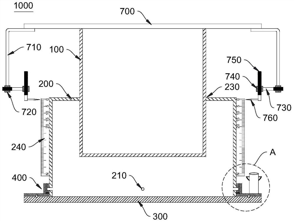
[0046] Please refer to figure 1 , this embodiment provides a sand box device 1000 for the construction of cast-in-place beams. The flask device 1000 includes: an inner cylinder 100 , an outer cylinder 200 , a bottom plate 300 and a rotating member 400 .

[0047] The outer cylinder 200 is installed on the bottom plate 300, and the inner cavity of the outer cylinder 200 is used for filling fine sand.

[0048] The inner cylinder 100 is engaged with the fitting opening 230 , and along the axial direction of the fitting opening 230 , the inner cylinder 100 is slidably mated with the outer cylinder 200 .

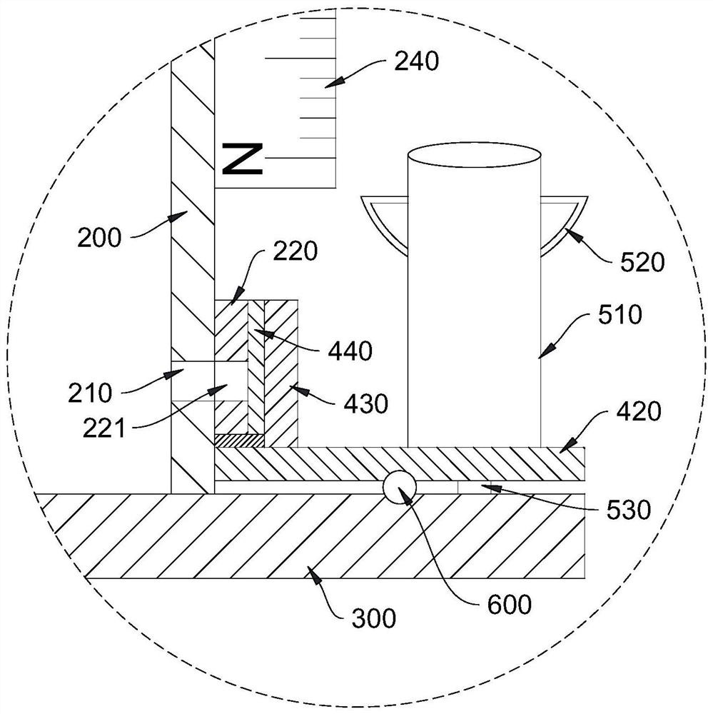
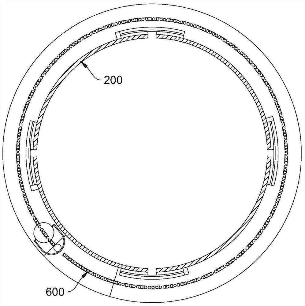
[0049] The rotating part 400 is ring-shaped, and the rotating part 400 is rotatably sleeved on the outer wall of the outer cylinder 200. The rotating part 400 is provided with a gap 410 for fine sand to pass through.

[0050] The rotating member 400 has a first rotational dead point and a second rotational dead point. When the rotating member 400 is at the first dead center of ...


PUM


Abstract

The invention discloses a sand box device for cast-in-place beam construction and a cast-in-place beam construction method, and relates to the field of engineering construction. The sand box device comprises an inner cylinder, an outer cylinder, a bottom plate and a rotating piece. The outer cylinder is installed on the bottom plate and provided with a sand discharging opening, and a matching opening is formed in the top of the outer cylinder. The inner cylinder is matched with the matching opening. The rotating piece is rotationally arranged on the outer wall of the outer cylinder in a sleeving mode and provided with a notch. When the rotating piece is located at a first rotating dead point, the rotating piece blocks the sand discharging opening. When the rotating piece is located at a second rotating dead point, the notch communicates with the sand discharging opening. The sand discharging speed is easy to control, sand blocking is effectively avoided, the elevation control precisionis high, and the support falling speed is easy to control. The construction method is simple, convenient, easy to control and operate and high in execution efficiency.

Description

technical field [0001] The invention relates to the field of engineering construction, in particular to a sand box device and a construction method for cast-in-place beams. Background technique [0002] The sand box is used in the construction of the cast-in-place prestressed concrete cover beam steel pipe column support system to support and unload the load. After the steel pipe column support system is erected and preloaded, the top elevation of the support system is adjusted to the construction design elevation, followed by the construction of the cast-in-place cover beam, and the support needs to be removed after the construction of the cast-in-place cover beam is completed. During this construction process, on the one hand, it is necessary to accurately adjust the elevation of the top of the support to the design elevation, and on the other hand, after the construction is completed, the support components must be removed safely and orderly from top to bottom. However, ...

Claims


Application Information

Patent Timeline
Patent Type & Authority Applications(China)
IPC IPC(8): E01D21/00E01D19/02E01D101/24E01D101/30
CPCE01D19/02E01D21/00E01D2101/24E01D2101/30
Inventor 张晓明张力文朱海江邓远新林东伟彭豪张子惠张洛川薛文明刘茜茜
Owner THE GUANGDONG NO 3 WATER CONSERVANCY & HYDRO ELECTRIC ENG BOARD CO LTD
Why Eureka
Try Eureka