Stroke adjustable energy-saving hydraulic pumping unit

An adjustable, pumping unit technology, applied in mechanical equipment, production fluids, wellbore/well components, etc., can solve the problems of cumbersome equipment installation and maintenance, high transportation and installation costs, and high self-energy consumption, and achieves simple structure and operation. The effect of low cost and increased profit margin

Inactive Publication Date: 2007-11-28
丁长良
View PDF0 Cites 6 Cited by
  • Summary
  • Abstract
  • Description
  • Claims
  • Application Information

AI Technical Summary

Problems solved by technology

At present, the pumping units used in oil extraction operations mainly include two types of beam pumping units and linear pumping units. The beam pumping units are the most widely used, and they mainly have the following defects in the working process: 1. The stroke is not adjustable , the oil pumping rate is low; 2. The entire equipment needs to be installed with tons of sliders and cranks, and the transportation and installation costs are high; 3. The installation and maintenance of the entire equipment is cumbersome, time-consuming and laborious; 4. Poor safety; 5. Low oil production efficiency
There are also a few oil fields that use linear pumping units. The disadvantages are that the motor power is too large, the energy consumption is high, and the operating cost is high.

Method used


Image

  • Stroke adjustable energy-saving hydraulic pumping unit
  • Stroke adjustable energy-saving hydraulic pumping unit

Examples


Embodiment Construction

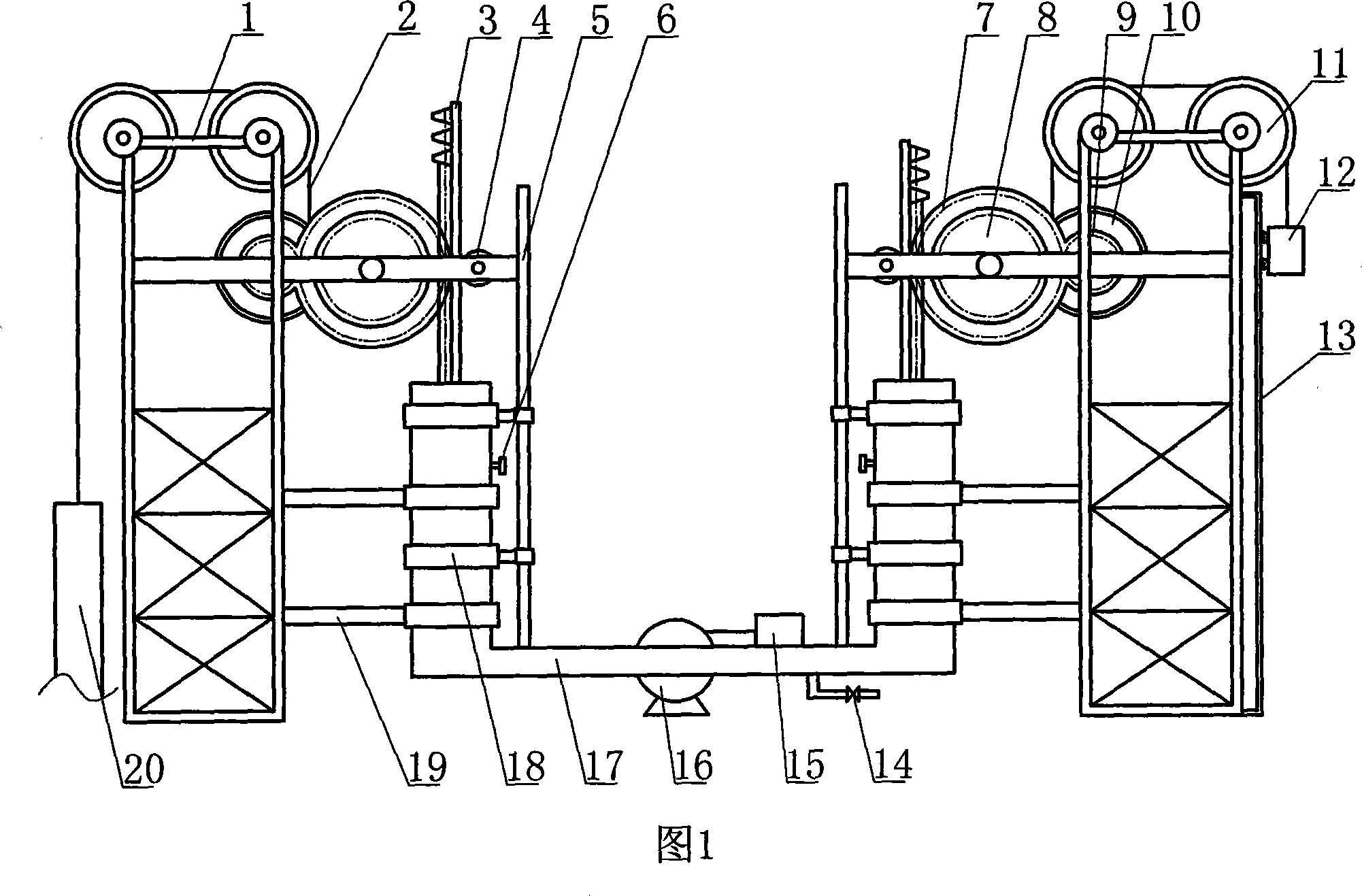
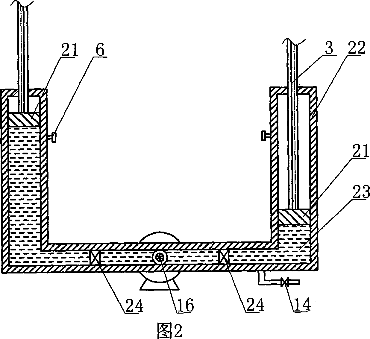
[0020] The present invention will be further described in detail below through the specific examples, the following examples are only descriptive, not restrictive, and cannot limit the protection scope of the present invention with this.

[0021] This energy-saving hydraulic pumping unit with adjustable stroke is composed of frame 1, gear set, hydraulic transmission mechanism 17, rack 3, sky wheel 11, lifting rope 2 and sucker rod 20, and is symmetrical on both sides of the hydraulic transmission mechanism. Two frames and two gear sets are installed, one frame is installed with sucker rods, and the other frame is installed with lifting box 12; the two gear sets are respectively meshed with the racks installed at both ends of the hydraulic transmission mechanism, and the two The gear train is all made up of driving gear 8, driven gear 9 and reel 10 and is fixed on the frame. The driving gear of the gear set is coaxially equipped with a different-diameter pinion 7, and the diame...


PUM


Abstract

The invention relates to an energy-saving hydraulic oil pumping unit with adjustable stroke used in oil field, comprising frame, gear group, hydraulic transmission mechanism, rack, head sheave, suspended-weight rope and oil pumping bar. Two frames are set at two sides of hydraulic transmission mechanism symmetrically. A gear group and two head sheaves are set on each frame. Two gear groups are mated with racks set at two ends of hydraulic transmission mechanism respectively. The gear group draws the oil pumping bar through the suspended-weight rope and the head sheave. Thereinto, the hydraulic transmission mechanism comprises communicating vessel, piston and hydraulic pump. A hydraulic pump is fixed in the communicating vessel and two pistons are set in cavities at two ends of communicating vessel respectively. Driving liquid is poured between two pistons in cavities of communicating vessel. The invention is provided with simple structure, scientific and reasonable design, adjustable stroke and punching time, convenient maintenance, dismounting and use, safe operation, high liquid production volume, little energy consumption and low operating cost. It is also provided with higher innovation.

Description

technical field [0001] The invention relates to a pumping unit used in an oil field, in particular to an energy-saving hydraulic pumping unit with adjustable stroke. Background technique [0002] The method of extracting oil from the formation is mainly divided into two categories: one is to use the energy of the formation itself to lift crude oil, which is called the self-spraying oil recovery method; the other is to artificially use mechanical equipment due to the lack of energy of the formation itself. Adding energy to the liquid in the well to lift crude oil to the ground is called artificial lift oil recovery or mechanical oil recovery. Pumping unit (commonly known as knocking machine) is a necessary mechanical equipment in mechanical oil recovery. The oil deeply hidden in the ground (or seabed) is pumped out through the oil pumping pipe by means of a pumping unit, so each crude oil production well needs at least one pumping unit. The working principle of the pumping u...

Claims


Application Information

Patent Timeline
Patent Type & Authority Applications(China)
IPC IPC(8): E21B43/00F16H47/02
Inventor 曹国江丁长良丁琳
Owner 丁长良
Why Eureka
Try Eureka