
Engine air bleed mechanism assembling method based on pushing jacking tool and pushing jacking tool

An assembly method and engine technology, applied to engine components, machines/engines, assembling machines, etc., can solve the problems of inconvenient operation, inconsistent coordination and cooperation, unreliable assembly, etc., to improve assembly quality, reduce human factors, The effect of reducing the failure rate of fracture

Active Publication Date: 2021-01-08
AECC AVIATION POWER CO LTD
View PDF47 Cites 0 Cited by
  • Summary
  • Abstract
  • Description
  • Claims
  • Application Information

AI Technical Summary

Problems solved by technology

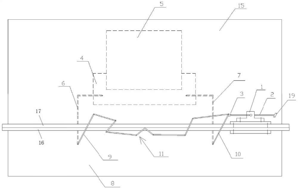
[0004] Since the bleed valve and the bleed main pipe are assembled outside the casing of the high-pressure compressor and inside the culvert casing, the rocker arm of the active lever of the bleed valve and the rocker arm of the follower lever of the bleed valve are used to adjust the bleed valve to the fully closed position. They are respectively located on the left and right sides of the engine outside near the horizontal position. In the prior art, the active rod rocker arm of the deflation valve and the follower rod rocker arm of the deflation valve are artificially supported so that the deflation valve is in a completely closed position, that is, the deflation valve is guaranteed to be in a completely closed position. The fitting surface of the exhaust main pipe is closely fitted in the circumferential direction, which is inconvenient to operate, and it is easy to cause unreliable assembly due to personnel fatigue, work negligence, or inconsistent coordination and cooperation during the assembly process.

Method used


Image

  • Engine air bleed mechanism assembling method based on pushing jacking tool and pushing jacking tool
  • Engine air bleed mechanism assembling method based on pushing jacking tool and pushing jacking tool
  • Engine air bleed mechanism assembling method based on pushing jacking tool and pushing jacking tool

Examples


Embodiment Construction

[0037] In order to make the purpose, technical solutions and advantages of the embodiments of the present invention clearer, the technical solutions of the present invention will be clearly and completely described below in conjunction with the accompanying drawings. Obviously, the described embodiments are part of the embodiments of the present invention, not all of them. the embodiment. Based on the embodiments of the present invention, all other embodiments obtained by persons of ordinary skill in the art without making creative efforts belong to the protection scope of the present invention.

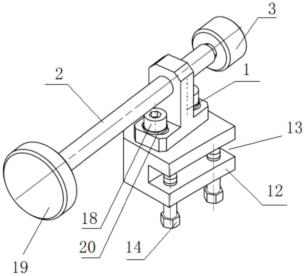
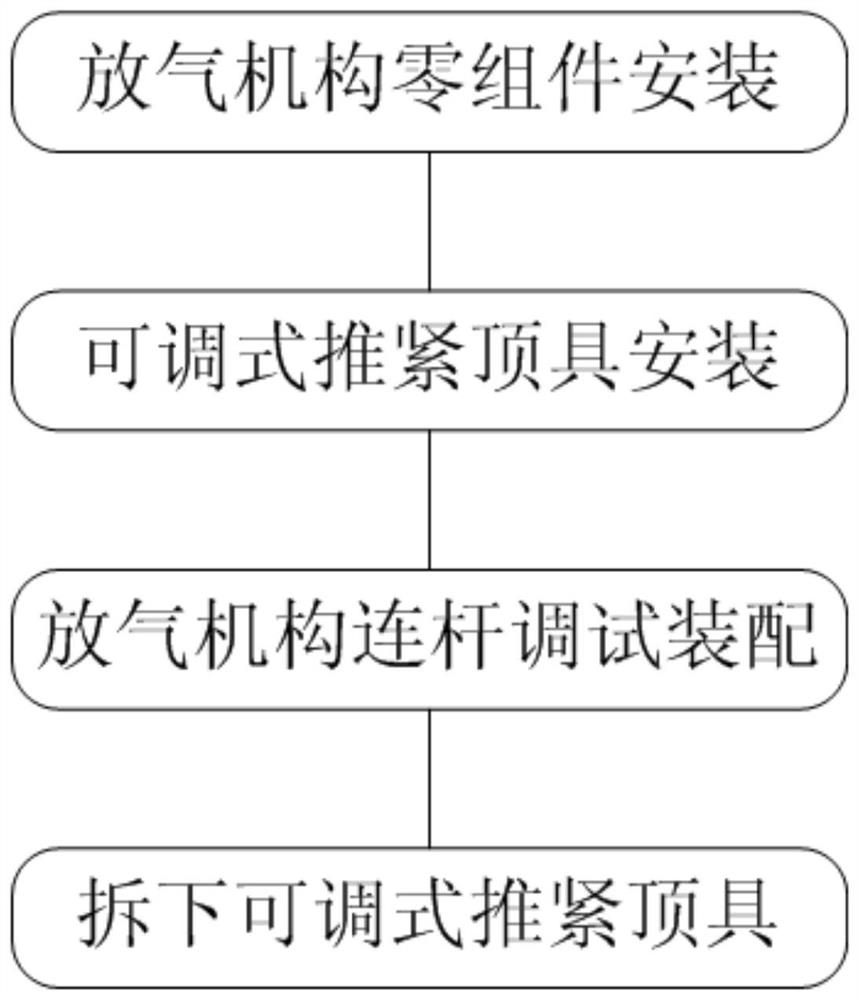
[0038] As a specific embodiment of the present invention, in combination with figure 1 as well as figure 2As shown, a push-up top tool includes a support 1, a push rod 2, a pressure block 3, an installation base 12, a first bolt 14, a second bolt 18 and an operating handle 19, and one side of the installation base 12 is provided with a mounting The groove 13 is provided with a fir...


PUM


Abstract

The invention discloses an engine air bleed mechanism assembling method based on a pushing jacking tool and the pushing jacking tool. An air bleed valve driving rod rocker arm and a air bleed valve driven rod rocker arm are adjusted, so that an air bleed valve and an air bleed main pipe are in a completely closed state; at the moment, a push rod, close to the position of the air bleed valve driving rod rocker arm and the position of the air bleed valve driven rod rocker arm, of the pushing jacking tool is rotated, thus, the air bleed valve driving rod rocker arm and the air bleed valve drivenrod rocker arm are tightly jacked by a pressing block and kept still; and the air bleed valve driving rod rocker arm and the air bleed valve driven rod rocker arm are connected through a multi-connecting-rod assembly, a first connecting rod of the multi-connecting-rod assembly is connected with the air bleed valve driving rod rocker arm at first, finally the length of the last connecting rod of the multi-connecting-rod assembly is adjusted, the last connecting rod of the multi-connecting-rod assembly is connected with the air bleed valve driven rod rocker arm, and assembling of an engine air bleed mechanism is completed. Through the engine air bleed mechanism assembling method based on pushing jacking tool and the pushing jacking tool, the assembly quality can be improved, and the failurerate of breakage of the air bleed valve driving rod or the air bleed valve driven rod is reduced.

Description

technical field [0001] The invention belongs to the field of assembly technology, and in particular relates to an assembly method of an engine deflation mechanism based on a push-up top tool and a push-up top tool. Background technique [0002] Both the active lever of the bleed valve and the follower lever of the bleed valve belong to the control lever of the bleed valve, and are the main components of the bleed mechanism of a certain type of engine. Specifically, there are four control rods for the deflation valve, one is the active rod of the deflation valve, the other is the follower rod of the deflation valve, and the other two are support rods, wherein the active rod of the deflation valve and the follower rod of the deflation valve Right on set. They are all installed in the outer casing of the intermediate casing, the inner end is fixed on the intermediate casing separation ring with a bracket, the outer end is fixed on the installation boss of the intermediate casi...

Claims


Application Information

Patent Timeline
Patent Type & Authority Applications(China)
IPC IPC(8): F01L1/18F01L1/46B23P21/00
CPCB23P21/00F01L1/18F01L1/46
Inventor 杜龙梅梁键王天谭陈林赵健王剑辛宇航郭晓玲
Owner AECC AVIATION POWER CO LTD
Learn More