Hose winding support

A technology for hose coils and winding racks, which is applied in the direction of pipe brackets, pipes/pipe joints/fittings, special distribution devices, etc., and can solve the problem of damaged hose coiling racks, railings or walls that cannot be hung from railings, etc. Can not get the convenience of use and other issues, to achieve the effect of improving convenience

Inactive Publication Date: 2003-09-24
KOTOBUKI TSUSHOU
View PDF0 Cites 3 Cited by
  • Summary
  • Abstract
  • Description
  • Claims
  • Application Information

AI Technical Summary

Problems solved by technology

[0004] But, in the use of above-mentioned existing hose winding frame, owing to be that suspension hook is fixed on the winding frame body, because the railing of corridor or the reason of the shape of wall, often have the obstacle such as railing or wall to make it impossible to move from When hanging from railings, etc., or the direction of hanging

Method used


Image

  • Hose winding support
  • Hose winding support
  • Hose winding support

Examples


Embodiment Construction

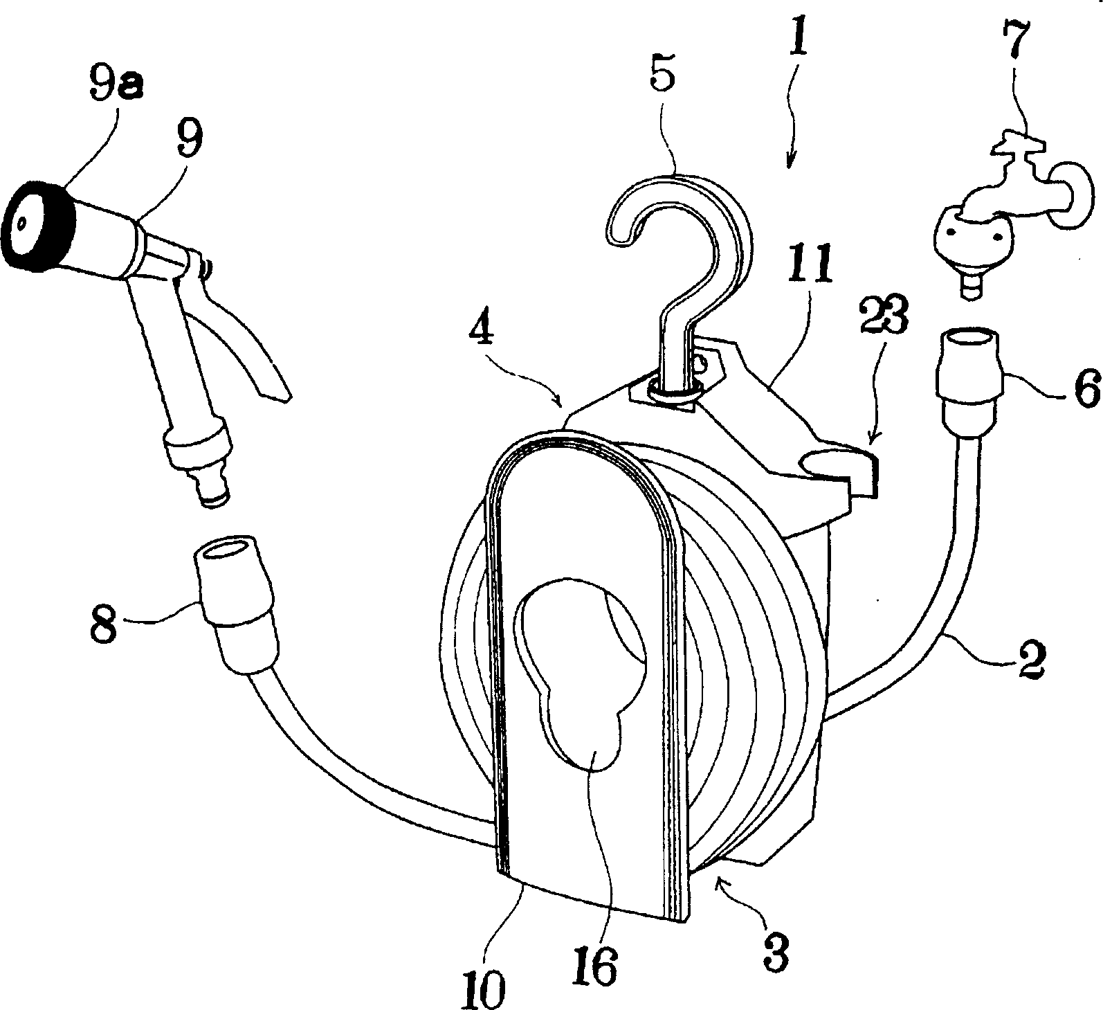
[0020] figure 1 The usage state of the hose reel 1 of the present invention is shown. The hose winding frame 1 is composed of a winding frame body 4 and a hook 5. The winding frame body 4 has a hose winding portion 3 for winding the hose 2; the hook 5 is installed on the winding frame body 4 the upper part. In the figure, 6 is a joint for a water tap, 7 is a water tap, 8 is a joint for a spray gun, and 9 is a sprinkling spray gun.

[0021] The hose reel 1 is designed to store the used hose 2 by winding the hose 2 around the hose reel 3 .

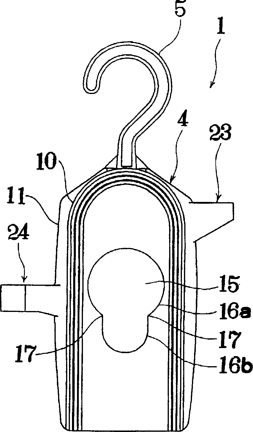
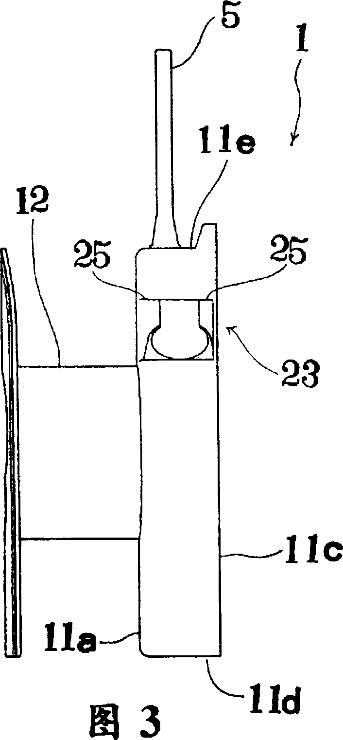
[0022] Such as Figure 1~6 As shown, the winding stand body 4 is a hollow cylindrical hose winding body 12 spanned approximately at the center of the front side wall body 10 and the rear side wall body 11 .

[0023] A spray gun storage portion 15 for storing the sprinkler gun 9 is formed in the hollow portion of the hose winding cylinder 12 .

[0024] The hose 2 is wound around the outer peripheral surface of the hose winding cylinder 1...


PUM


Abstract

The invention provides a very convenient hose reel, which can freely rotate and shake freely on the reel body (4) having a hose reel (3) for winding the hose (2). The hook (5) is set up.

Description

technical field [0001] The present invention relates to hose reels. Background technique [0002] In the existing hose winding frame, a hose winding cylinder for winding the hose is formed on the winding frame body; meanwhile, a hook is fixed on the upper part of the winding frame body. [0003] In the state where the hose is wound and stored in the hose winding cylinder, the hose winding frame is suspended from the railing or wall of the corridor. [0004] But, in the use of above-mentioned existing hose reel frame, owing to be that suspension hook is fixed on the reel frame body, because the railing of corridor or the reason of the shape of wall, often have the obstacle such as railing or wall to make can't from When the railing or the like is suspended, or the direction of the suspension is restricted, good usability cannot be obtained. [0005] In addition, when the hose winding frame is suspended outdoors, due to the influence of wind, etc., the connecting part of the...

Claims


Application Information

Patent Timeline
IPC IPC(8): B67D7/40B65H75/36B65H75/40
CPCB65H75/366B65H75/4463B65H2701/33
Inventor 高城寿雄池田启介
Owner KOTOBUKI TSUSHOU
Why Eureka
Try Eureka