Insulator wire fixing and lifting device

A wire fixing and wire lifting technology, applied in the direction of hoisting device, overhead line/cable equipment, clockwork mechanism, etc., can solve the problem of increasing the labor intensity of aerial workers, reducing the safety factor of aerial work, and affecting the construction efficiency of wire racks. and other problems, to achieve the effect of convenient modular storage, convenient disassembly, and simple structure

Active Publication Date: 2021-01-08
国网山东省电力公司昌乐县供电公司 +1
View PDF8 Cites 0 Cited by
  • Summary
  • Abstract
  • Description
  • Claims
  • Application Information

AI Technical Summary

Problems solved by technology

[0004] In order to solve the current problem of lifting the wires on the crossarm by manpower, it will not only increase the labor intensity of the high-altitude workers, waste labor, but also reduce the safety factor of high-altitude operations, which is more dangerous; and manual lifting of the wires requires certain experience and proficiency. For unskilled operators, it will seriously affect the construction efficiency of wire erection. The invention provides an insulator wire fixing and lifting device

Method used


Image

  • Insulator wire fixing and lifting device
  • Insulator wire fixing and lifting device
  • Insulator wire fixing and lifting device

Examples


Embodiment 1

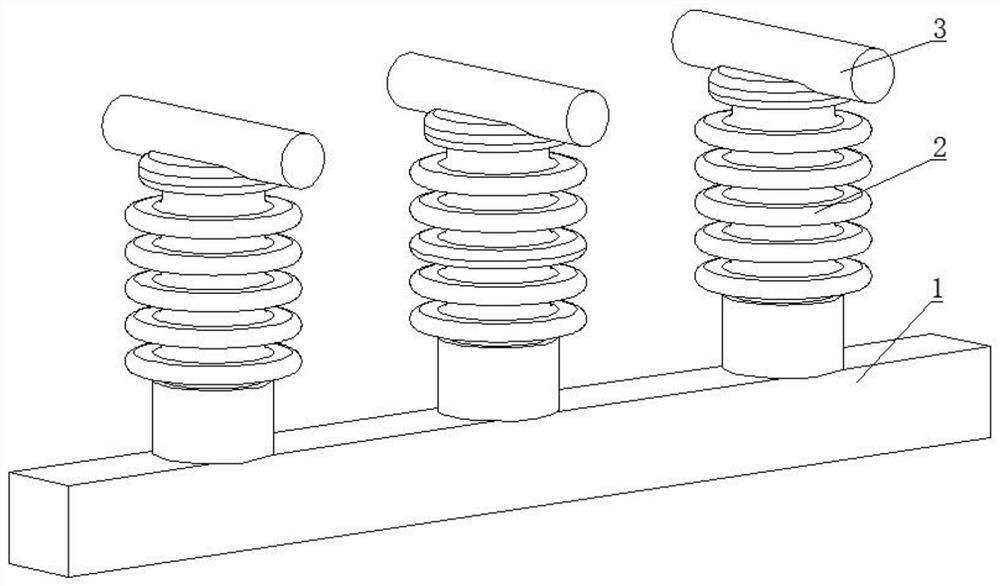
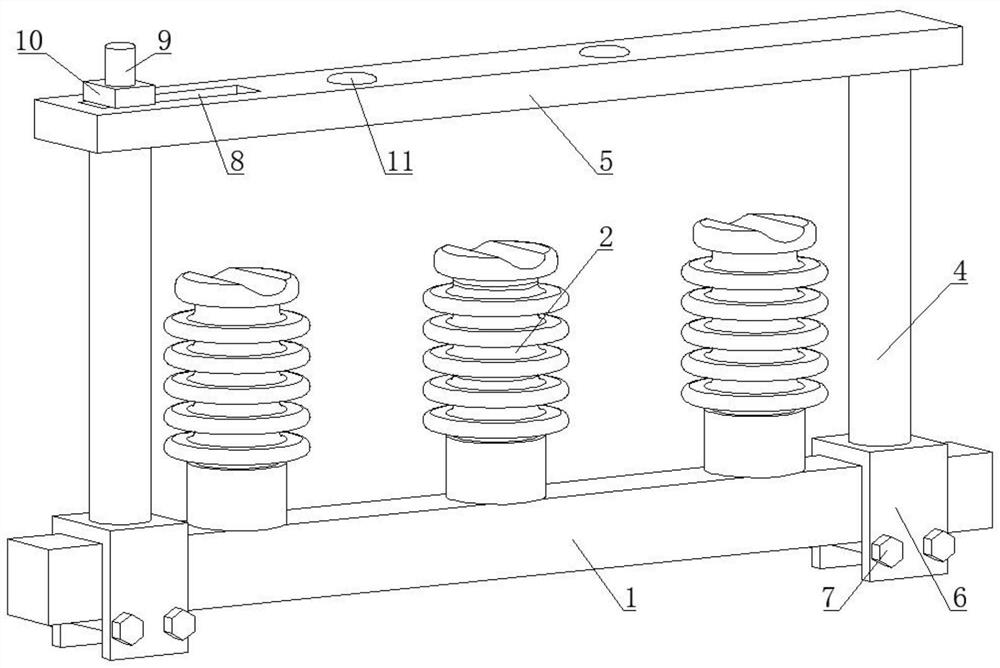
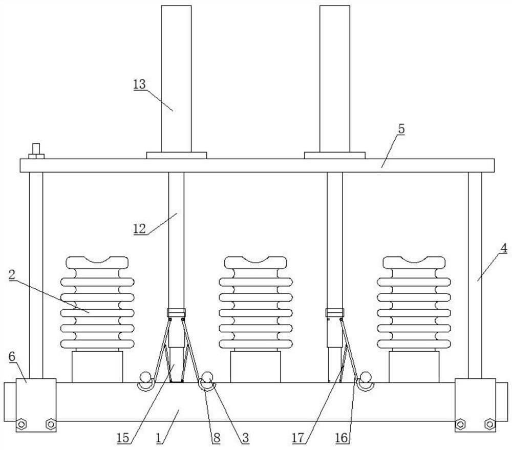
[0029] As shown in the drawings, an insulator wire fixing and lifting device includes a cross arm 1, an insulator 2, an upright lifting rod 12 and a "冂"-shaped bracket, and the insulator 2 is vertically installed on the upper side of the cross arm 1 , and three are arranged side by side at intervals for supporting and fixing the wires; the bracket includes a horizontal horizontal frame 5 and two vertical columns 4, and the horizontal frame 5 and the vertical columns 4 form a "冂"-shaped bracket, the The upright column 4 is detachably connected and installed with the end of the cross arm 1 through a connecting piece. The horizontal frame 5 is provided with a lifting device that drives the lifting rod 12 to lift. The guide hole 11 for the lifting guide of the rod 12, the lifting rod 12 is arranged in the middle of the adjacent insulator 2; the lower end of the lifting rod 12 is connected with a supporting telescopic cylinder 15, and the upper part of the cylinder body of the suppo...

Embodiment 2

[0039] Such as Figure 9 As shown, this embodiment is basically the same as Embodiment 1, the difference is that: the lifting device is a screw lifter 21, the lifting rod 12 is a threaded rod, and the screw lifter 21 is provided with a rocker 22. Rotate the rocker 22, drive the lifting rod 12 to go up and down through the screw lifter 21, the transmission is stable and reliable, and can be rotated manually, the operation is convenient, time-saving and labor-saving; safety.

[0040] In the initial state of the insulator wire fixing and lifting device, the lifting rod is in the state of descending and extending, the supporting telescopic cylinder is in the state of extending, and the wire lifting hook is at the lower side of the corresponding wire; the lifting device drives the lifting rod to lift, and the wire lifting hook is aligned with the wire. The support lifts up until it is higher than the insulator; the support telescopic cylinder retracts, driving the support rod to m...


PUM


Abstract

The invention discloses an insulator wire fixing and lifting device, and belongs to the technical field of electric power. The device comprises a cross arm, an insulator, a vertical lifting rod and asupport, and the insulator is mounted at the upper side of the cross arm; the support comprises a transverse frame and a stand column, the stand column and the cross arm are detachably installed through a connecting piece, and the transverse frame is provided with a lifting device driving the lifting rod to ascend and descend; and the lower end of a supporting telescopic cylinder is rotationally connected with a supporting rod, the end, away from the supporting telescopic cylinder, of the supporting rod is hinged to the lifting rod, and the end, away from the supporting telescopic cylinder, ofthe lifting rod is connected with a wire lifting hook. The whole structure is simple, operation is convenient, operators do not need to directly lift the wire, labor intensity is greatly reduced, labor force is saved, the safety coefficient of aloft work is improved, and safety is good; and the wire erection efficiency is high, and the practicability is high.

Description

technical field [0001] The invention belongs to the technical field of electric power, in particular to an insulator wire fixing and lifting device. Background technique [0002] When erecting the wires on the pole, first install the cross arm on the pole, and install the insulators supporting the wires in an array on the cross arm, then pre-set the wires on the cross arms between the adjacent insulators, and finally need to adjust the cross arms on the cross arm. The wire is lifted up to the top of the insulator, limited by the groove on the top of the insulator, and the wire and the insulator are fixed by the clamp, such as figure 1 shown. [0003] However, in the upward lifting of the wires on the cross-arm, the operator usually lifts them up by manpower, which will not only increase the labor intensity of the high-altitude workers, waste labor, but also reduce the safety factor of high-altitude operations, which is more dangerous; Moreover, manual lifting of the wires ...

Claims


Application Information

Patent Timeline
Patent Type & Authority Applications(China)
IPC IPC(8): H02G1/02B66D1/12B66D1/08B66D1/02
CPCH02G1/02B66D1/08B66D1/12B66D1/02
Inventor 张爱国于晓东钟国斌徐凤岐徐良孙小朋沈继勇许秀芹范兆凯唐恺郭焕连王鲁昌刘军许丽君黄佳丽于琪肖会张万隆
Owner 国网山东省电力公司昌乐县供电公司
Why Eureka
Try Eureka