Rotor dismounting method and device

A technology in a rotor and a stator, applied in the field of rotor disassembly and installation, can solve the problems of permanent magnet damage of the rotor, collision between the stator and the rotor, and can not be reused.

Active Publication Date: 2021-01-08
XIAN AEROSPACE PRECISION ELECTROMECHANICAL INST
View PDF4 Cites 0 Cited by
  • Summary
  • Abstract
  • Description
  • Claims
  • Application Information

AI Technical Summary

Problems solved by technology

[0003] The purpose of the present invention is to solve the problem that when the stator and rotor of the inner rotor type permanent magnet synchronous motor are separated by the traditional method, bumps will occur between the stator and the rotor, causing the rotor to For the problem that the permanent magnets of the permanent magnets are damaged and cannot be reused, a method and device for dismantling the rotor are provided

Method used


Image

  • Rotor dismounting method and device
  • Rotor dismounting method and device

Examples


Embodiment 1

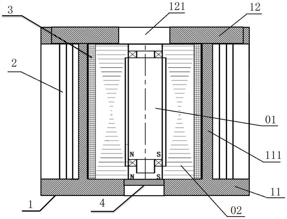
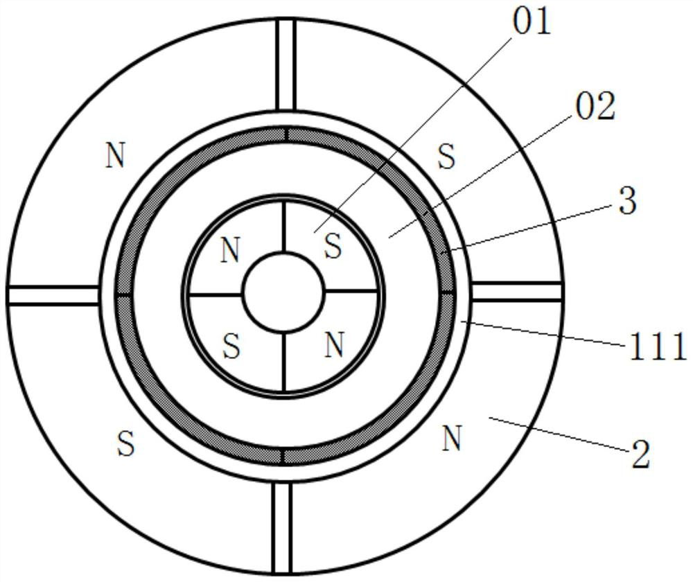
[0067] like figure 1 , figure 2 As shown, the device includes a fixing tool 1 , a radial magnetic force offset unit 2 , a sensor unit 3 , and an axial magnetic force action unit 4 .

[0068] The fixed tooling 1 includes a bracket 11 and a cover plate 12 provided with a central hole 121. The bracket 11 includes an inner barrel 111 for placing the motor to be disassembled. The cover plate 12 is arranged above the bracket 11. The central hole 121 is just in front of the motor to be disassembled to remove the end cover. One end, and the diameter of the central hole 121 is larger than the outer diameter of the rotor 01 of the motor to be disassembled, and smaller than the outer diameter of the stator 02 of the motor to be disassembled, which is used to limit the axial movement of the stator 02, and the rotor 01 can be taken out through the central hole 121.

[0069] The radial magnetic force offset unit 2 includes n tile-shaped magnetic body assemblies, and the n tile-shaped magn...

Embodiment 2

[0078] see figure 1 , figure 2 As shown, the device includes a fixing tool 1 , a radial magnetic force offset unit 2 , a sensor unit 3 , and an axial magnetic force action unit 4 .

[0079] The fixed tooling 1 includes a bracket 11 and a cover plate 12 provided with a central hole 121. The bracket 11 includes an inner barrel 111 for placing the motor to be disassembled. The cover plate 12 is arranged above the bracket 11. The central hole 121 is just in front of the motor to be disassembled to remove the end cover. One end, and the diameter of the central hole 121 is larger than the outer diameter of the rotor 01 of the motor to be disassembled, and smaller than the outer diameter of the stator 02 of the motor to be disassembled, which is used to limit the axial movement of the stator 02, and the rotor 01 can be taken out through the central hole 121.

[0080] The radial magnetic force offset unit 2 includes n tile-shaped electromagnets, and the n tile-shaped electromagnets ...


PUM


Abstract

The invention relates to a rotor dismounting method and device, and aims to solve the problem that when a stator and a rotor of an inner rotor type permanent magnet synchronous motor are separated byadopting a traditional method, the stator and the rotor collide with each other, so that a permanent magnet of the rotor is damaged and cannot be reused. The method comprises the following steps of: (1) disassembling an end cover at one end of a to-be-disassembled motor, circumferentially arranging radial magnetic force counteracting units on the outer side of the to-be-disassembled motor, whereinmagnetic poles of the radial magnetic force counteracting units and magnetic poles of a rotor are consistent in number and are in one-to-one correspondence, and meanwhile the corresponding magnetic poles are identical in polarity; 2) adjusting the magnetic force of each magnetic pole of the radial magnetic force counteracting unit to counteract the radial attraction force of each magnetic pole ofthe rotor to the stator, thereby balancing the position of the rotor in the stator; and 3) taking the rotor out of the stator. The device comprises a fixing tool used for placing a to-be-disassembledmotor, a radial magnetic force counteracting unit used for applying magnetic force to the circumference of a rotor on the outer side of the to-be-disassembled motor, and a sensor unit used for sensing the magnetic force action condition.

Description

technical field [0001] The invention relates to a method and a device for disassembling a rotor. Background technique [0002] The inner rotor type permanent magnet synchronous motor is mainly composed of stator, rotor, end cover and other components. The stator is made of laminated sheets, which has good magnetic conductivity. The rotor can be made into a solid form, or it can be made of laminated sheets. It is made of permanent magnet materials, and due to the effect of permanent magnets, the rotor has a large radial attraction to the stator. When the working conditions change suddenly and the motor fails, it is necessary to separate the stator and rotor of the motor. Due to the structural reasons of the motor, the traditional separation method will cause bumps between the stator and the rotor, resulting in damage to the permanent magnet of the rotor and failure. Reuse. Contents of the invention [0003] The purpose of the present invention is to solve the problem that...

Claims


Application Information

Patent Timeline
Patent Type & Authority Applications(China)
IPC IPC(8): H02K15/00H02K15/03H02K15/16
CPCH02K15/0006H02K15/03H02K15/165
Inventor 李吉兴谢宗晟曹宽
Owner XIAN AEROSPACE PRECISION ELECTROMECHANICAL INST
Why Eureka
Try Eureka