A surface marking positioning spraying device for noodles

A surface marking and spraying device technology, which is applied in the direction of dough processing, dough embossing machine, baking, etc., can solve the problems of low efficiency and manpower consumption, and achieve the effect of high degree of automation, improved efficiency and reasonable design

Active Publication Date: 2021-09-03
WUHAN POLYTECHNIC UNIVERSITY
View PDF11 Cites 0 Cited by
  • Summary
  • Abstract
  • Description
  • Claims
  • Application Information

AI Technical Summary

Problems solved by technology

[0006] The purpose of the present invention is to solve the problem of labor-intensive and low efficiency in the prior art, and propose a surface marking positioning spraying device

Method used


Image

  • A surface marking positioning spraying device for noodles
  • A surface marking positioning spraying device for noodles
  • A surface marking positioning spraying device for noodles

Examples


Embodiment 1

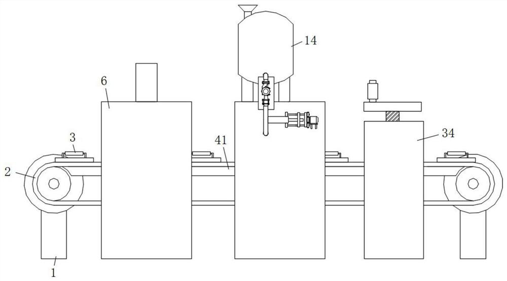
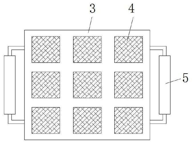
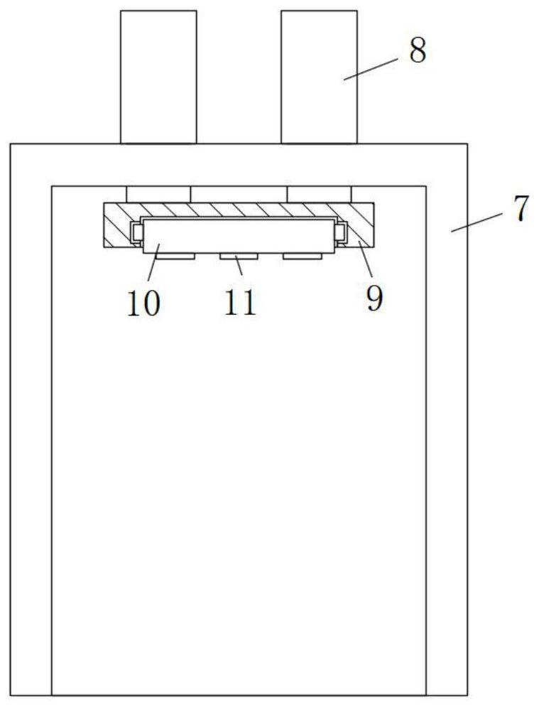
[0036] refer to Figure 1-8 , a surface mark positioning spraying device for noodles, including a mounting base 1, a conveyor belt 2 is installed on the upper end of the mounting base 1, and a limiter mold is fixed on the belt surface of the conveyor belt 2, and a plurality of limiter molds are arranged and evenly distributed on the conveyor belt 2 belt On the upper surface, a feeding tray 3 is placed on the belt surface of the conveyor belt 2, and a rectangular hole is opened through the top surface of the feeding tray 3. The inner wall of the rectangular hole is fixed with a partition net 4, and the front and rear sides of the feeding tray 3 are also fixed with lifters. Handle 5, conveyer belt 2 side is provided with marking mechanism 6, and marking mechanism 6 comprises work frame-7, and work frame-7 outer top front and rear sides are all connected with electric telescopic rod 8 by screw, and the output end of electric telescopic rod 8 wears The top surface of the working f...

Embodiment 2

[0039] Such as figure 1 As shown, this embodiment is basically the same as Embodiment 1. Preferably, the lower side of the upper belt surface of the conveyor belt 2 is also provided with an abutment plate 41, and the top surface of the abutment plate 41 is attached to the bottom of the upper belt surface of the conveyor belt 2, and the front and back of the abutment plate 41 Sides are all fixed on the inner wall of work frame one 7, work frame two 15 and work frame three 35 by screws.

[0040] In this embodiment, when in use, the lower side of the upper belt surface of the conveyor belt 2 is also provided with a support plate 41, thereby playing the effect of supporting the feeding tray 3, and then making the embossing and oiling operations of the pasta more stable and easy. It ensures the stability of the device operation.

Embodiment 3

[0042] Such as figure 1 and 2 As shown, this embodiment is basically the same as Embodiment 1. Preferably, there are multiple feeding trays 3 that are evenly distributed on the top of the belt surface of the conveyor belt 2, and there are four mounting seats 1 that are fixed on the working surface in a rectangular shape. On the top, there are multiple partitions 4 and they are distributed in a matrix on the top surface of the feeding tray 3 .

[0043] In this embodiment, a plurality of feeding trays 3 are evenly arranged on the conveyor belt 2, so as to realize the continuous production of pasta.


PUM


Abstract

The invention discloses a surface mark positioning spraying device for noodle points, which comprises a mounting seat, a conveyor belt is installed on the upper end of the mounting seat, a feeding tray is placed on the belt surface of the conveyor belt, and a rectangular hole is opened through the top surface of the feeding tray. The inner wall of the shaped hole is fixed with a partition net, the front and rear sides of the feeding tray are also fixed with a lifting handle, and a marking mechanism is arranged on one side of the conveyor belt. All are fixed with electric telescopic rods through screws. The output end of the electric telescopic rods passes through the top surface of the work frame and is fixedly connected with a fixed plate. There is also a mounting groove on the bottom surface of the fixed plate. A mounting plate is slidably connected to the inner wall of the groove, and an embossing mold is fixed on the bottom surface of the mounting plate. The invention has reasonable design and high degree of automation, can realize the continuous marking and uniform oiling operation of pastries, and provides a certain guarantee for the high-quality and rapid production of pastries.

Description

technical field [0001] The invention relates to the technical field of pastry production equipment, in particular to a pastry surface mark positioning spraying device. Background technique [0002] Pasta is the main part of Chinese cooking. It is famous for its long history, exquisite production, rich variety and diverse flavors. Before baking pasta, it is often necessary to stamp and oil the end surface, which requires the use of marking and oiling equipment. [0003] After searching, the patent with application number 201810426602.1 discloses a pastry embossing machine, which includes a conveying device for conveying pasta for embossing, a guide assembly arranged above the conveying device and a die pushing The conveying device includes a conveyor belt wheel set and a horizontal transmission belt connected between the conveyor belt wheel sets. The bottom end of the transmission belt is supported by a support plate. The die pushing device includes a main frame and a die se...

Claims


Application Information

Patent Timeline
Patent Type & Authority Patents(China)
IPC IPC(8): A21C11/08A21C9/04A21C9/08
CPCA21C9/04A21C9/08A21C11/08
Inventor 张燕鹏张维农胡志雄孙威庄坤
Owner WUHAN POLYTECHNIC UNIVERSITY
Why Eureka
Try Eureka