
A special-shaped valve plate grinding equipment

A special-shaped valve plate and equipment technology, which is used in grinding/polishing equipment, metal processing equipment, grinding machines, etc., can solve the problems of difficult automatic grinding, low grinding efficiency, high labor intensity, etc., and achieves good grinding effect and wide grinding range. , the effect of high efficiency

Active Publication Date: 2021-11-23
六安中达信息科技有限公司
View PDF12 Cites 0 Cited by
  • Summary
  • Abstract
  • Description
  • Claims
  • Application Information

AI Technical Summary

Problems solved by technology

[0002] The valve plate is a device that controls the passage of liquid to reduce its pressure or change its flow and flow direction. The valve plate needs to have a strong sealing effect. The valve plate is processed into a finished product by strong punching, and the installation hole formed by stamping on the valve plate For installation, due to the difference in the product structure of the valve plate, the structure of the valve plate will have a greater difference. For the direction or circular valve plate, it is more convenient to grind the side surface, and for some opposite-shaped valve plates, the outer ring of the valve plate There will be grooves or bumps on the surface, which is difficult to be automatically polished by ordinary equipment. Usually, manual grinding is used, which has low grinding efficiency and high labor intensity.

Method used


Image

  • A special-shaped valve plate grinding equipment
  • A special-shaped valve plate grinding equipment
  • A special-shaped valve plate grinding equipment

Examples


Embodiment Construction

[0028] The following will clearly and completely describe the technical solutions in the embodiments of the present invention with reference to the accompanying drawings in the embodiments of the present invention. Obviously, the described embodiments are only some, not all, embodiments of the present invention. Based on the embodiments of the present invention, all other embodiments obtained by persons of ordinary skill in the art without making creative efforts belong to the protection scope of the present invention.

[0029] In the description of the present invention, it should be noted that the orientation or positional relationship indicated by the terms "vertical", "upper", "lower" and "horizontal" are based on the orientation or positional relationship shown in the drawings, and are only for It is convenient to describe the present invention and simplify the description, but does not indicate or imply that the device or element referred to must have a specific orientati...


PUM


Abstract

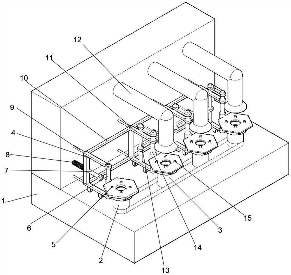
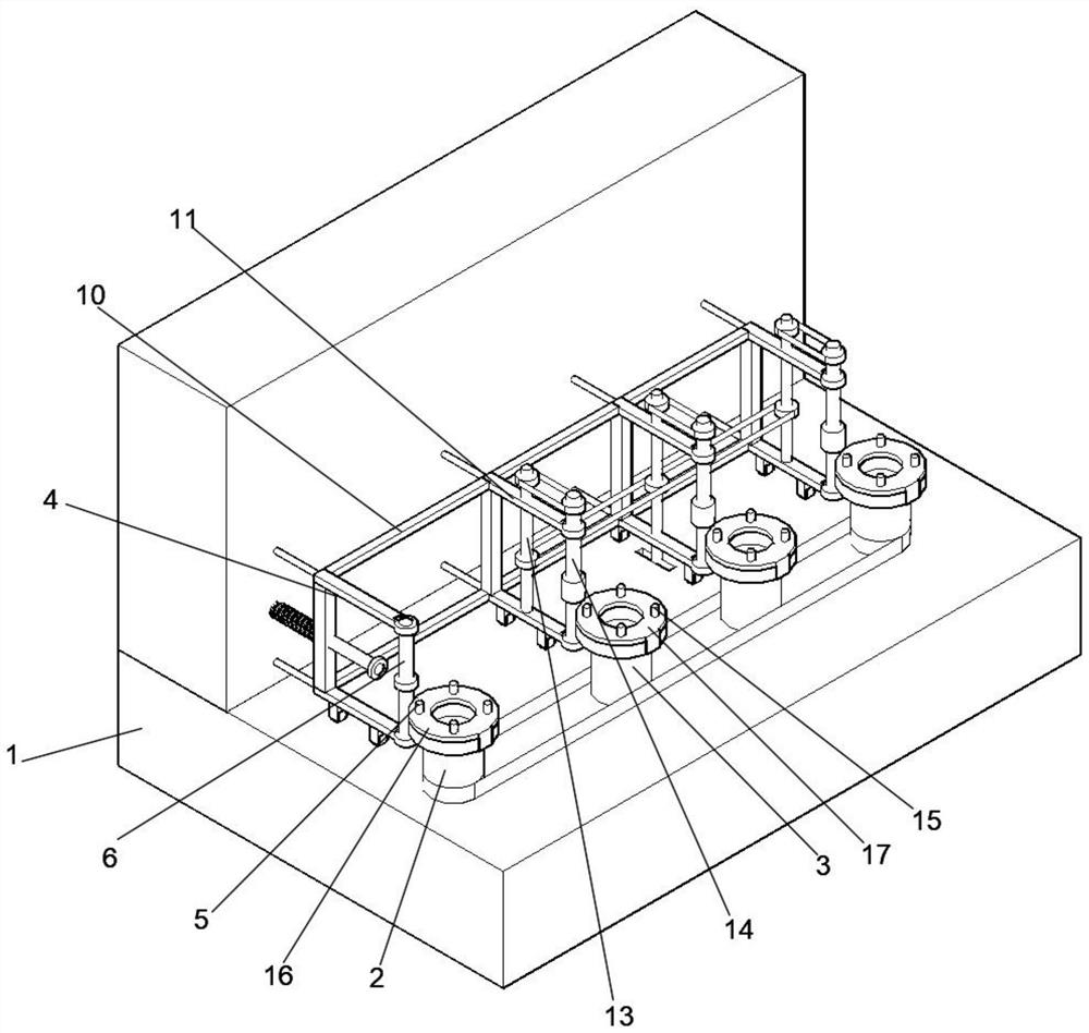
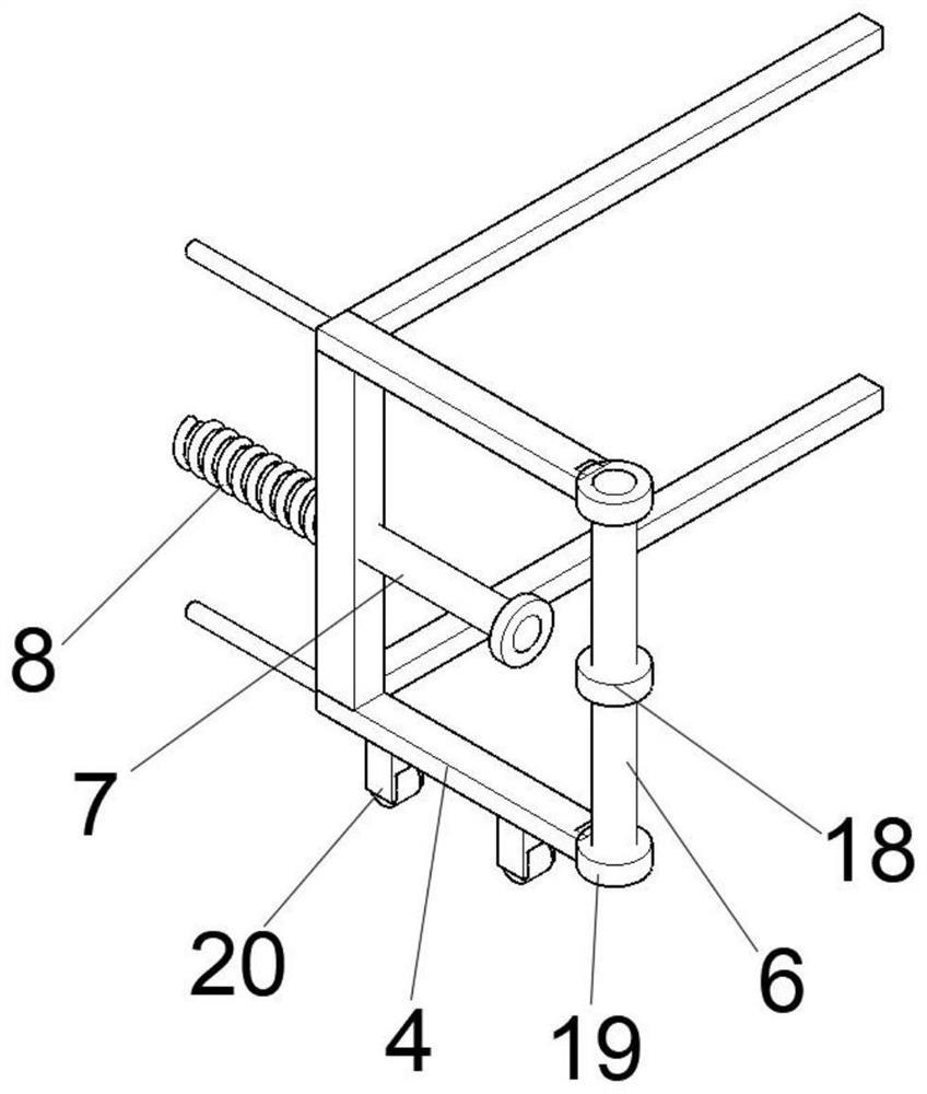
The invention discloses a special-shaped valve plate grinding equipment, which includes an operation table, on which a track simulation mechanism and a grinding mechanism are arranged; the track simulation mechanism includes a first rotating table, and the first rotating table is provided with The first fixed base, the first rotating shaft is rotatably connected with a first support frame, and the first support frame is slidingly connected with the operating table through a first guide rod, and the end of the first guide rod close to the operating table is sleeved with a second A support spring; the grinding mechanism includes a second turntable, the second turntable is rotatably connected to the first turntable through a chain, and the second support frame is connected to the first support frame through a connecting frame; the second turntable of the present invention A rotating shaft moves along the outer contour of the valve mold, and the first grinding rod moves and grinds along the outer contour of the valve to be polished. The corresponding grinding mold can be replaced according to different valves, and the valves of different shapes can be polished. wide.

Description

technical field [0001] The invention relates to the technical field of valve plates, in particular to a special-shaped valve plate grinding equipment. Background technique [0002] The valve plate is a device that controls the passage of liquid to reduce its pressure or change its flow and flow direction. The valve plate needs to have a strong sealing effect. The valve plate is processed into a finished product by strong punching, and the installation hole formed by stamping on the valve plate For installation, due to the difference in the product structure of the valve plate, the structure of the valve plate will have a greater difference. For the direction or circular valve plate, it is more convenient to grind the side surface, and for some heterosexual valve plates, the outer ring of the valve plate There will be grooves or bumps on the surface, which is difficult to be automatically polished by ordinary equipment. Usually, manual grinding is used, which has low grinding...

Claims


Application Information

Patent Timeline
Patent Type & Authority Patents(China)
IPC IPC(8): B24B17/02B24B27/00B24B41/06B24B47/20
CPCB24B17/026B24B27/0023B24B27/0076B24B41/061B24B47/20
Inventor 任振宇张家龙
Owner 六安中达信息科技有限公司
Learn More