
Pile holding machine

A technology of pile holding machine and pile column, which is applied in sheet pile wall, construction, infrastructure engineering and other directions, can solve the problems of pile pipe separation from pile holding mechanism, damage, pile pipe vibration and other problems.

Pending Publication Date: 2021-01-12
SOUTH CHINA MARINE MACHINERY
View PDF1 Cites 0 Cited by
  • Summary
  • Abstract
  • Description
  • Claims
  • Application Information

AI Technical Summary

Problems solved by technology

[0004] However, when the pile-holding mechanism of this invention is holding the pile pipe tightly, there is a gap between the pile-holding mechanism and the pile, and the fixing between the pile-holding mechanism and the pile is only realized by a plurality of rollers, and one side of the pile-holding mechanism There is a gap, so that there is a large gap between the pile holding mechanisms. Therefore, during the piling process, the pile pipe will vibrate. If the swing cylinder fails and the swing arm becomes loose, the pile pipe will be separated from the pile holding mechanism. , which may cause serious damage to

Method used


Image

  • Pile holding machine
  • Pile holding machine
  • Pile holding machine

Examples


Embodiment Construction

[0024] The present invention will be described in further detail below in conjunction with the accompanying drawings and specific embodiments.

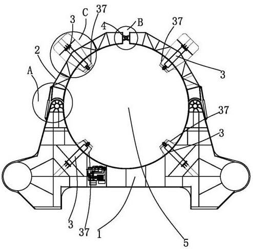
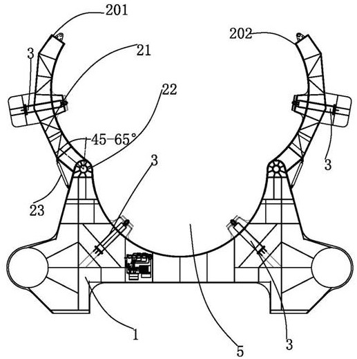
[0025] Such as Figure 1 to Figure 7 As shown, a pile holding machine includes a base 1 on which a pile holding device 2 , an oil cylinder device 3 and a locking device 4 are arranged.

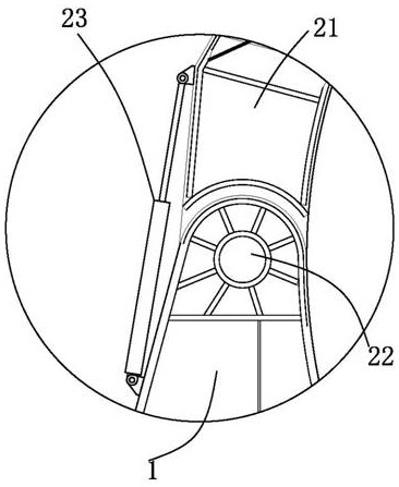
[0026] Such as Figure 1 to Figure 3 As described, the pile holding device 2 includes an arm 21, a bearing seat 22 and an arm cylinder 23, the bearing seat 22 is installed on the base 1, the arm 21 is connected to the bearing seat 22, and the arm cylinder 23 is connected to the arm 21 and the base 1; the locking device 4 includes a locking oil cylinder 41, a fixed seat 42, a lock pin 43, a locking fixed plate 44 and a movable fixed plate 45, and the locking oil cylinder 41 is installed on the lock through the fixed seat 42 On the fixed plate 44, the piston rod 411 of the locking cylinder 41 is arranged in the fixed seat 42 and connected to the lock ...


PUM


Abstract

The invention provides a pile holding machine. The pile holding machine comprises a base; a pile holding device, an oil cylinder device and a locking device are arranged on the base, the pile holdingdevice comprises a holding arm, a bearing seat and an arm opening oil cylinder, the bearing seat is installed on the base, the holding arm is connected with the bearing seat, and the arm opening oil cylinder is connected with the holding arm and the base; and the locking device comprises a locking oil cylinder, a fixing base, a lock pin, a locking fixing plate and a movable fixing plate, the locking oil cylinder is installed on the locking fixing plate through the fixing base, and a piston rod of the locking oil cylinder is arranged in the fixing base and connected with the lock pin. When thepile holding machine is used, the holding arm is unfolded, when a pile enters a pile area, the holding arm is closed, after the completion of closing of the holding arm, the pile holding device is locked through the locking device, thus a pile column is surrounded and prevented from being separated from the pile holding device even if the pile column vibrates under the action of the locking devicein the pile driving process, and the stability is good.

Description

technical field [0001] The invention relates to the technical field of offshore operations, in particular to a pile holding machine. Background technique [0002] One of the difficulties in offshore construction is the installation of piles. Using a pile hammer to forcefully strike the piles and insert them into the underwater mud, that is, the so-called "pile driving". To ensure the verticality of the pile, therefore, it is necessary to use a pile holder to balance the verticality of the pile during the piling process. [0003] In the patent document with the Chinese patent application number 201710038038.1 and the publication date of 2017.05.10, an offshore wind power operation platform is disclosed, which includes a positioning pipe frame, and an operation console is installed on the positioning pipe frame, and at least A group of pile-holding mechanisms are installed; the pile-holding mechanism includes two positioning plates symmetrically arranged, the positioning plat...

Claims


Application Information

Patent Timeline
IPC IPC(8): E02D13/00E02D13/04
CPCE02D13/00E02D13/04
Inventor 姚典王江陈懿谷文平郭安罗韦淋睦邹韬刘忠饶王海江潘学光赵旭陈世业
Owner SOUTH CHINA MARINE MACHINERY
Learn More