A grass scraping device for preventing the blade shaft of a rotary cultivator from tangling grass
A rotary tiller and knife shaft technology, applied in the field of rotary tiller, can solve the problems of grass scraping device failure, entanglement, and weeds cannot be removed, and achieve the effects of improving connection stability, easy disassembly operation, and convenient replacement operation
- Summary
- Abstract
- Description
- Claims
- Application Information
AI Technical Summary
Problems solved by technology
Method used
Image
Examples
Embodiment 1
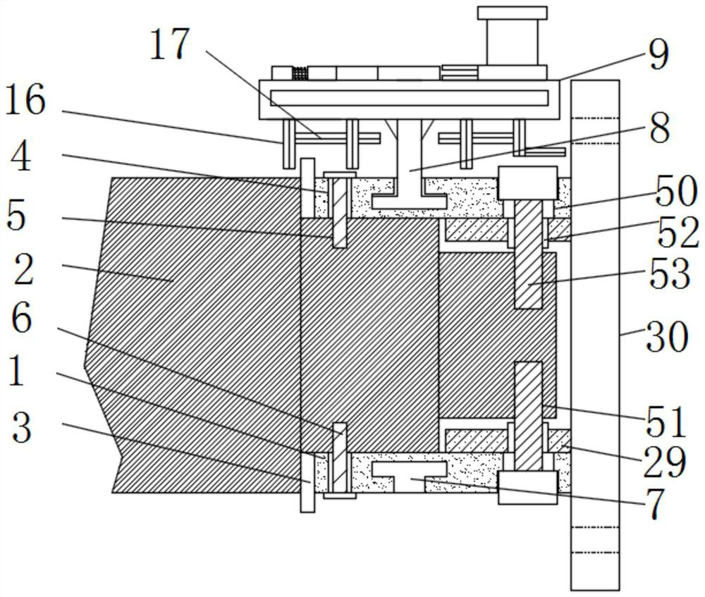
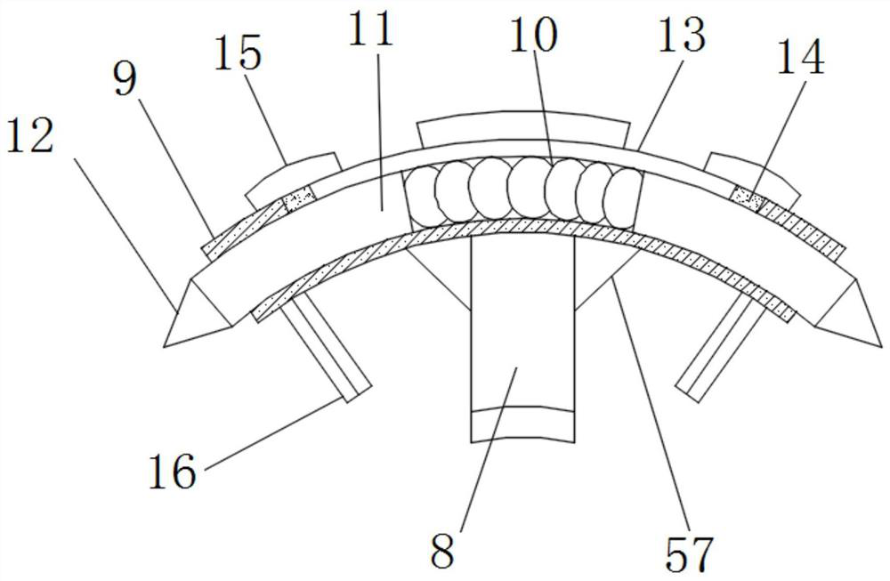
[0040] see Figure 1-10 , according to an embodiment of the present invention, a grass scraping device for preventing the blade shaft of a rotary cultivator from tangling grass includes two arc-shaped plates 1, and the two arc-shaped plates 1 can form a cylinder, and the arc-shaped plates 1 can form a cylinder. 1 are connected by a connecting mechanism, the two arc-shaped plates 1 are located on the outer surface of the port of the cutter shaft 2, and one side of the arc-shaped plates 1 is fixedly connected with a bonding plate 3, and the rubber material used by the bonding plate 3, The fitting plate 3 is in contact with the port of the cutter shaft 2 , a through hole 4 is opened on the outer surface of the arc-shaped plate 1 and close to the fitting plate 3 , and the cutter shaft 2 is close to the through hole 1 4 There is a screw hole 5 at the place, and the port of the connecting bolt one 6 penetrates the through hole one 4 and is threadedly connected with the screw hole 5;...
Embodiment 2
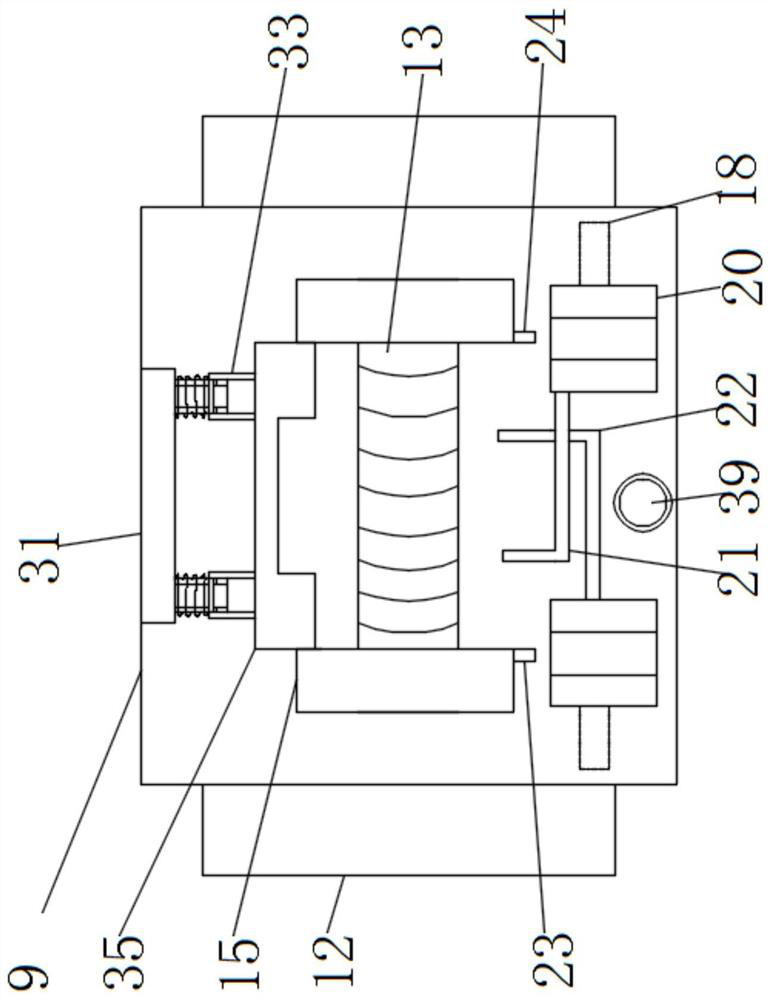
[0046] see Figure 3-6 , the fixing mechanism includes a fixing plate 31 , a second sleeve 32 , a third sleeve 33 , a second spring 34 and a limit plate 35 , and a fixing plate 31 is fixedly connected to one side of the top of the fixing box 9 , and the fixing plate 31 is close to One side of the movable opening 13 is fixedly connected with two second sleeves 32 , the outer surface of the second sleeve 32 is sleeved with a third sleeve 33 , the third sleeve 33 and the fixing plate 31 A second spring 34 is connected between them, the second spring 34 is wrapped around the outer surface of the second sleeve 32, and the side of the third sleeve 33 away from the fixing plate 31 is fixedly connected to the limiting plate 35. The fixing mechanism The second connecting block 15 can be fixed and the current state of the connecting block 15 can be maintained, so that the second connecting block 15 cannot be moved, and the second sleeve 32 and the third sleeve 33 are connected with the ...
Embodiment 3
[0048] see image 3 and Figure 11-12 , the limit mechanism 1 includes a threaded sleeve 1 39, a threaded block 40, a support sleeve 41, a spring 3 42, a limit rod 2 43 and a stop block 44. The top of the fixed box 9 is located between the movable block 20. A threaded sleeve 1 39 is fixedly connected between the two parts, a threaded block 40 is threadedly connected to the inside of the threaded sleeve 1 39, and a support sleeve 41 is fixedly connected to the top of the threaded block 40. The second limit rod 43 is connected, the top of the second limit rod 43 is fixedly connected with a block 44, the two sides of the support sleeve 41 are opened with the second limit slot 45, and the second limit slot 45 is provided with a limit Block three 46, the limit block three 46 is fixedly connected with the limit rod two 43, the limit mechanism one can cooperate with the rotary tiller body to limit the fixed box 9, so that the fixed box 9 does not follow the cutter shaft 2 Rotate to...
PUM
 Abstract
Description
Claims
Application Information
 - R&D
- Intellectual Property
- Life Sciences
- Materials
- Tech Scout
- Unparalleled Data Quality
- Higher Quality Content
- 60% Fewer Hallucinations
Browse by: Latest US Patents, China's latest patents, Technical Efficacy Thesaurus, Application Domain, Technology Topic, Popular Technical Reports.
© 2025 PatSnap. All rights reserved.Legal|Privacy policy|Modern Slavery Act Transparency Statement|Sitemap|About US| Contact US: help@patsnap.com


