Synchronization unit for shift transmission

A technology of synchronizing unit and transmission

Inactive Publication Date: 2021-01-12
HOERBIGER ANTRIEBSTECHN HLDG
View PDF0 Cites 0 Cited by
  • Summary
  • Abstract
  • Description
  • Claims
  • Application Information

AI Technical Summary

Problems solved by technology

Component vibrations within the synchronization unit lead on the one hand to undesired noise generation and on the other hand to undesired damage to components of the synchronization unit

Method used


Image

  • Synchronization unit for shift transmission
  • Synchronization unit for shift transmission
  • Synchronization unit for shift transmission

Examples


Embodiment Construction

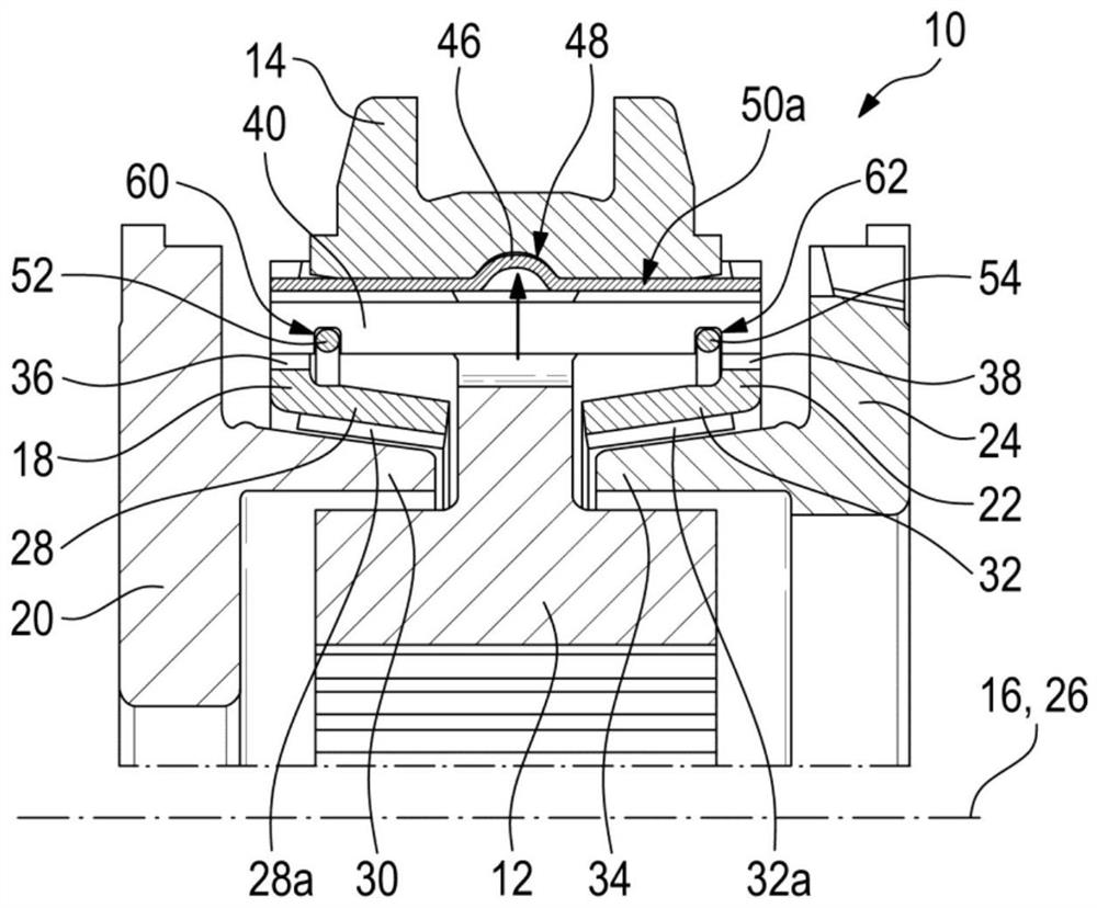
[0060] figure 1 A synchronization unit 10 for a shift transmission of a motor vehicle is shown.

[0061] This synchronization unit includes a hub 12 which can be coupled in a rotationally fixed and axially fixed manner to a transmission shaft, not shown in detail. The sliding sleeve 14 is connected in a known manner to the hub 12 in a non-rotatable, but slidable manner along the central axis 16 of the synchronization unit 10 .

[0062] Furthermore, the synchronization unit 10 comprises a first synchronization ring 18 , by means of which the rotational speed of the hub 12 can be synchronized with the rotational speed of the first clutch body 20 .

[0063] Furthermore, a second synchronizing ring 22 is provided, by means of which the rotational speed of the hub 12 can be synchronized with the rotational speed of the second clutch body 24 .

[0064] The first unison ring 18 and the second unison ring 22 are arranged coaxially and rotatably about a unison ring axis 26 which corr...


PUM


Abstract

The invention relates to a synchronization unit (10) for a gearshift transmission, comprising a first synchronizing ring (18), a second synchronizing ring (22), at least one carrier plate (40) and twoannular springs (52, 54). The first synchronizing ring (18) and the second synchronizing ring (22) each have a friction cone section (28, 32) and a locking tooth section (36, 38). Here, one of the annular springs (52, 54) is arranged on the radially outer side of the friction cone section (28) of the first synchronizing ring (18) and the other of the annular springs (52, 54) is arranged on the radially outer side of the friction cone section (32) of the second synchronizing ring (22). Furthermore, the two annular springs (52, 54) are coupled in the axial direction by means of a carrier plate(40).

Description

technical field [0001] The invention relates to a synchronizing unit for a shift transmission, the synchronizing unit has a first synchronizing ring, a second synchronizing ring, at least one carrier plate and two annular springs, wherein the first synchronizing ring and the second synchronizing ring are Arranged axially and rotatably about the synchronizing ring axis, and the first synchronizing ring and the second synchronizing ring each have a friction cone section with a radially inner friction surface and each have a locking tooth section, and the first synchronizing ring The and second synchronizing rings are arranged opposite each other such that the locking toothing sections are arranged at opposite axial ends of these synchronizing rings. Background technique [0002] Such synchronization units are known in the prior art. [0003] Here, the carrier plate is used for a so-called presynchronization at the beginning of the shifting process. Due to the sliding of the ...

Claims


Application Information

Patent Timeline
Patent Type & Authority Applications(China)
IPC IPC(8): F16D23/06F16D23/02F16F15/133
CPCF16D23/06F16D23/025F16F15/1332F16D2023/0631F16D2023/0625F16D2023/0656F16D23/04
Inventor 沃尔夫冈·福尔克安德列亚斯·登普夫勒尤尔根·宾德尔维尔纳·菲尔古特帕特里克·费舍尔
Owner HOERBIGER ANTRIEBSTECHN HLDG
Why Eureka
Try Eureka