Discharge valve assembly, compressor and air conditioner

An exhaust valve and component technology, applied in the field of compressors, can solve the problems of complex exhaust valve structure, difficult processing and production of exhaust valve, long response path, etc.

Active Publication Date: 2022-06-28
ZHUHAI GREE REFRIGERATION TECH CENT OF ENERGY SAVING & ENVIRONMENTAL PROTECTION
View PDF10 Cites 0 Cited by
  • Summary
  • Abstract
  • Description
  • Claims
  • Application Information

AI Technical Summary

Problems solved by technology

[0002] The compressor generally has an exhaust port on the flange, and an elastic valve plate is used to block the exhaust port. One end of the elastic valve plate is fixed on the flange, and the other end of the elastic valve plate is pre-loaded under the action of the elastic force of the valve plate. Pressure on the outside of the exhaust port, when the compressor is running, the valve plate will frequently collide with the flange at a relatively fast speed. Big
[0003] In order to solve the above technical problems, the Chinese invention patent application with the publication number CN110985347A discloses a rotary exhaust valve and an air-conditioning compressor. The valve plate 6 of this solution will not collide with the valve seat 1. However, this solution requires The relatively complex fluid channel 5 is processed on the seat 1, which makes the processing and production of the exhaust valve more difficult, and the structure of the exhaust valve is more complicated; moreover, the response path of the opening of the valve plate 6 in this scheme is longer, and the opening of the valve plate 6 The reaction is relatively slow, which can easily lead to poor exhaust

Method used


Image

  • Discharge valve assembly, compressor and air conditioner
  • Discharge valve assembly, compressor and air conditioner
  • Discharge valve assembly, compressor and air conditioner

Examples


Embodiment Construction

[0032] Examples of exhaust valve assemblies, compressors and air conditioners:

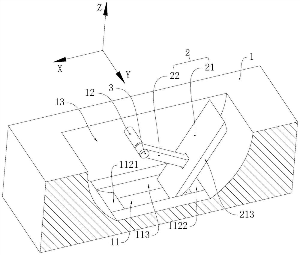
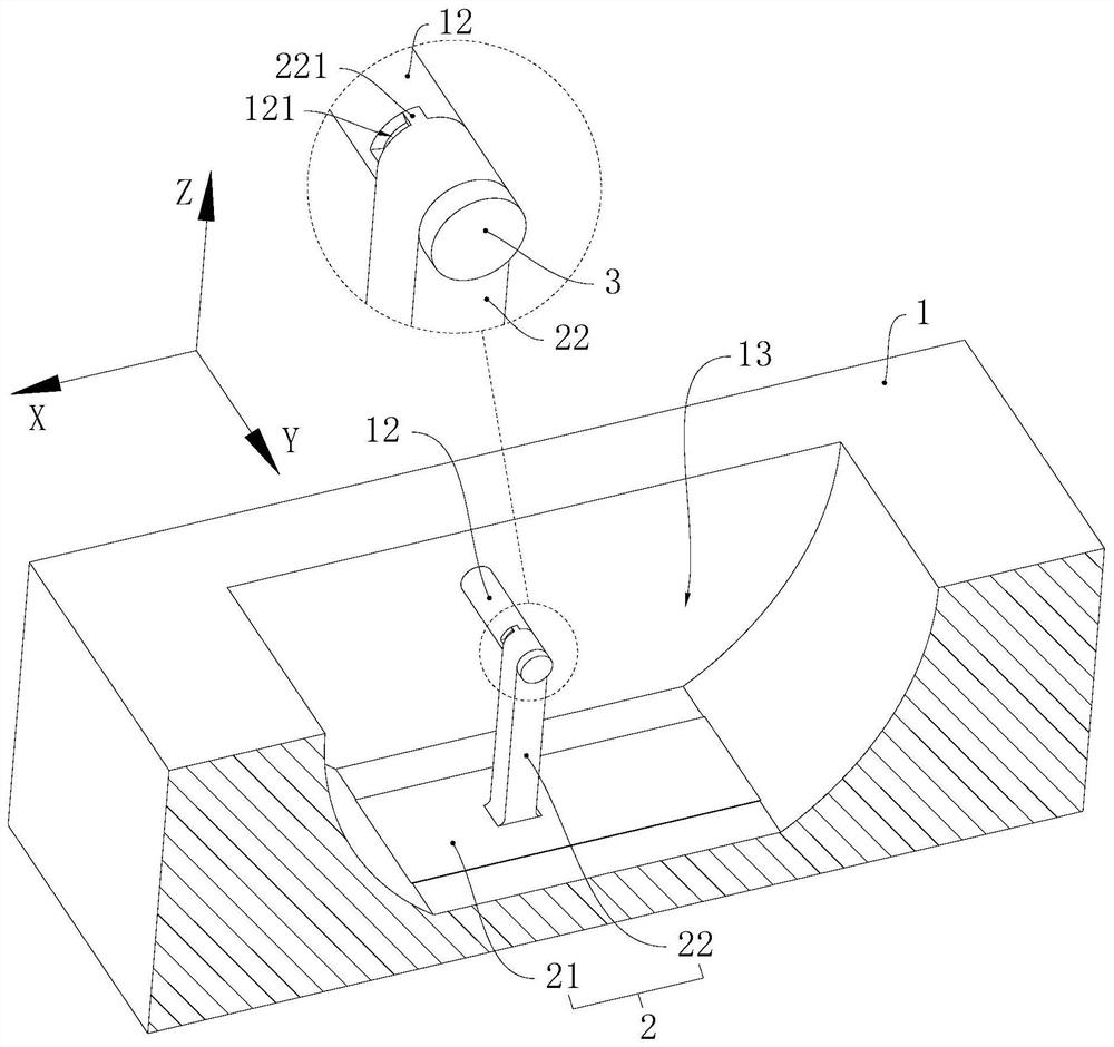
[0033] of this embodiment Figure 1 to Figure 5 A unified spatial rectangular coordinate system (right-handed system) is used to represent the azimuth relationship between the components, wherein the Z-axis direction in this embodiment is the first direction, and the Z-axis direction is the vertical direction. The Y-axis direction is the second direction, and the X-axis direction in this embodiment is the third direction.

[0034] The air conditioner of this embodiment includes the compressor of this embodiment, and the compressor of this embodiment includes the exhaust valve assembly of this embodiment.

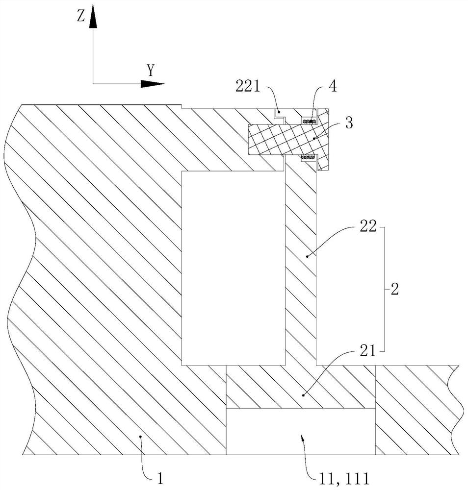
[0035] Please refer to figure 1 , the compressor assembly includes a base body 1, a movable body 2, a pin 3 and a torsion spring 4 (see image 3 ), the base body 1 is the flange of the compressor, and the base body 1 is provided with an exhaust hole 11 penetrating along the Z-axis direction, ...


PUM


Abstract

The invention relates to the field of compressors, and provides an exhaust valve assembly, a compressor and an air conditioner. The exhaust valve assembly includes a base body and a movable body, and the base body is provided with an exhaust hole penetrating along the first direction; the movable body is rotatably connected to the base body, and the axis of rotation of the movable body relative to the base body is the first axis, and the first axis is along the first axis. Two directions, the second direction intersects with the first direction; the movable body and the base body are provided with a limit fit structure at the rotational connection, the limit fit structure includes a first limit part and a second limit part, and the first limit part is fixed On the base, the second limiting part is fixed on the movable body; the first limiting part and the second limiting part are distributed along the circumferential direction of the first axis; the second limiting part abuts against the first limiting part , the movable body blocks the vent holes and projects along the first direction, and the projected areas of the vent holes on both sides of the first axis are different in size. The movable body is not easy to be fatigued and damaged due to collision and impact, and it is beneficial to reduce the running noise of the exhaust valve assembly.

Description

technical field [0001] The invention relates to the field of compressors, in particular to an exhaust valve assembly, a compressor and an air conditioner. Background technique [0002] The compressor generally opens an exhaust port on the flange, and uses an elastic valve plate to block the exhaust port. Pressed on the outside of the exhaust port, when the compressor is running, the valve plate will frequently collide with the flange at a faster rate. big. [0003] In order to solve the above-mentioned technical problems, the Chinese invention patent application with publication number CN110985347A discloses a rotary exhaust valve and an air-conditioning compressor. The valve plate 6 of this solution will not collide with the valve seat 1. However, this solution needs to be in the valve The more complex fluid channel 5 is processed on the seat 1, which makes the processing and production of the exhaust valve more difficult, and the structure of the exhaust valve is more co...

Claims


Application Information

Patent Timeline
Patent Type & Authority Patents(China)
IPC IPC(8): F16K15/03F16K27/02F16K1/20F16K47/02F04C29/12
CPCF16K15/033F16K27/0227F16K1/2014F16K47/02F04C29/12
Inventor 胡远培徐嘉杨欧翔柳鹏高津
Owner ZHUHAI GREE REFRIGERATION TECH CENT OF ENERGY SAVING & ENVIRONMENTAL PROTECTION
Why Eureka
Try Eureka