Carbon fiber transmission shaft with high torque
A transmission shaft and carbon fiber technology, applied in the transmission shaft field, can solve the problems of accelerated aging and oxidation of the transmission shaft, and the ineffective cleaning of dust, water and pollutants, achieves comprehensive and effective cleaning, is innovative, and ensures effective effect used
- Summary
- Abstract
- Description
- Claims
- Application Information
AI Technical Summary
Problems solved by technology
Method used
Image
Examples
Embodiment 1
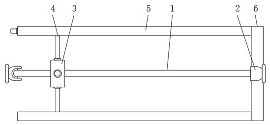
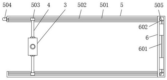
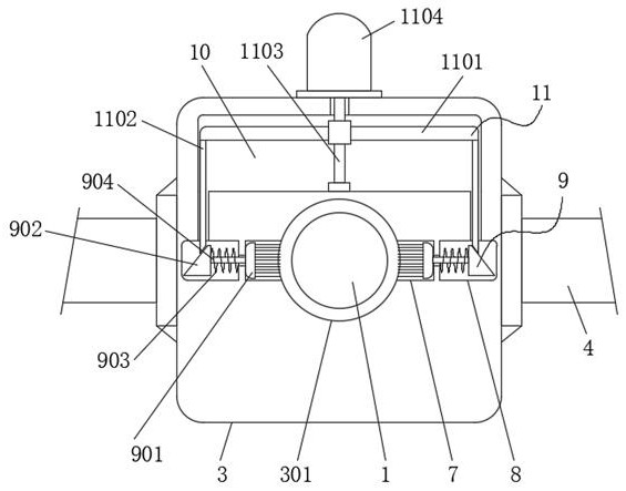
[0021] Embodiment one, by Figure 1 to Figure 3 Given, the present invention includes a transmission shaft body 1, universal joints 2 are installed at both ends of the transmission shaft body 1, a cover block 3 is sleeved on the surface of the drive shaft body 1, and connecting blocks 3 are fixedly installed on both sides of the cover block 3. Rod 4, through the setting of the connecting rod 4, the sleeve block 3 can be stably adjusted on the surface of the transmission shaft body 1, and one end of the two connecting rods 4 is equipped with a mounting plate 5, and one end of the two mounting plates 5 is fixed A transmission connecting plate 6 is installed, and the middle part of the cover block 3 is symmetrically provided with a storage groove 7, and a reset groove 8 is installed on one side of the two storage grooves 7, and a reset cleaning mechanism 9 is installed between the storage groove 7 and the reset groove 8, Through the setting of the receiving groove 7 and the reset...
Embodiment 2
[0022] Embodiment two, on the basis of embodiment one, by image 3 Given, the middle part of the cover block 3 is provided with a perforation 301, the cover block 3 is sleeved on the surface of the transmission shaft body 1 through the perforation 301, and the receiving groove 7 is symmetrically opened inside the perforation 301, so that the transmission shaft body 1 can be effectively carried out. Install and turn.
Embodiment 3
[0023] Embodiment three, on the basis of embodiment one, by figure 2 Given, the opposite sides of the two mounting plates 5 are provided with moving card slots 501, the insides of the two moving card slots 501 are rotatably installed with threaded shafts 502, and the surfaces of the two threaded shafts 502 are screwed with moving blocks 503 , the moving block 503 is slidingly clamped inside the moving card slot 501, the first bevel gear 505 is fixedly installed on one end of the two threaded shafts 502, and the one ends of the two connecting rods 4 are respectively fixed to one side of the two moving blocks 503 The other end of one of the mounting plates 5 is equipped with a first motor 504, and the output end of the first motor 504 is connected to the other end of one of the threaded shafts 502, so that the movement adjustment can be effectively carried out to make the block 3 move.
PUM
 Abstract
Description
Claims
Application Information
 - R&D
- Intellectual Property
- Life Sciences
- Materials
- Tech Scout
- Unparalleled Data Quality
- Higher Quality Content
- 60% Fewer Hallucinations
Browse by: Latest US Patents, China's latest patents, Technical Efficacy Thesaurus, Application Domain, Technology Topic, Popular Technical Reports.
© 2025 PatSnap. All rights reserved.Legal|Privacy policy|Modern Slavery Act Transparency Statement|Sitemap|About US| Contact US: help@patsnap.com


