
Positioning and temporary supporting stable unloading device for net rack hoisting and using method thereof

A temporary support and unloading device technology, applied in the direction of pillars, transportation and packaging, load hanging components, etc., can solve the problems of local rod overstress, node connection damage, structural collapse, etc., to ensure balance and stability, Ensure stability and prevent dislocation movement

Pending Publication Date: 2021-01-15
浙江中南绿建科技集团有限公司
View PDF0 Cites 2 Cited by
  • Summary
  • Abstract
  • Description
  • Claims
  • Application Information

AI Technical Summary

Problems solved by technology

[0002] At present, grid structures are often used in many airports, stations, gymnasiums and other building structures. This type of structure has the advantages of small space force, light weight, high rigidity, and good seismic performance, but it faces difficulties in construction and installation. The problem of one-time installation in place, the usual solution is to use a temporary support frame for block hoisting. This method involves the unloading of the original structure before the removal of the temporary support frame. Large deflection, local member overstress, node connection damage, even lead to structural collapse in severe cases

Method used


Image

  • Positioning and temporary supporting stable unloading device for net rack hoisting and using method thereof
  • Positioning and temporary supporting stable unloading device for net rack hoisting and using method thereof
  • Positioning and temporary supporting stable unloading device for net rack hoisting and using method thereof

Examples


Embodiment Construction

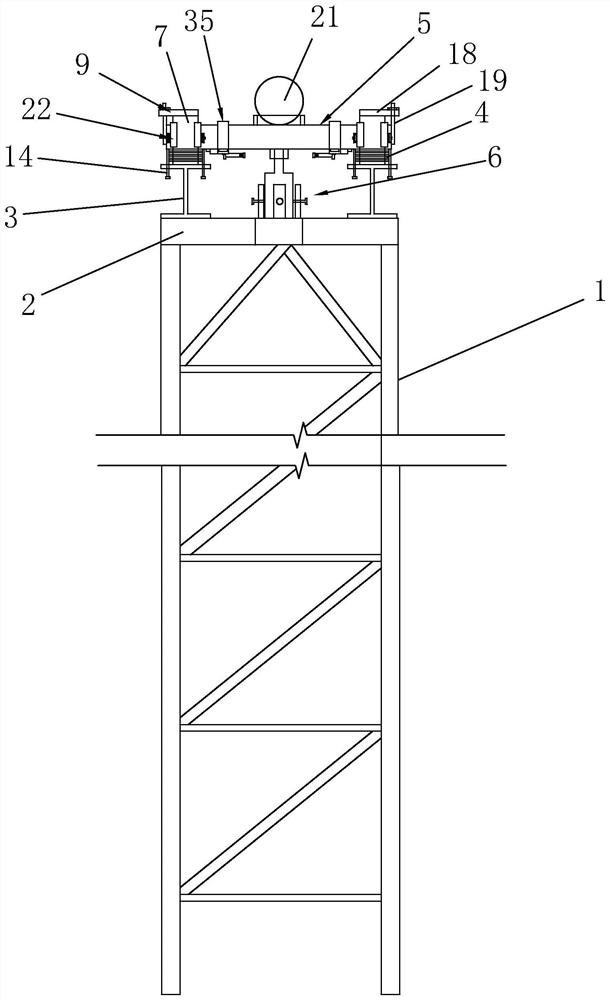
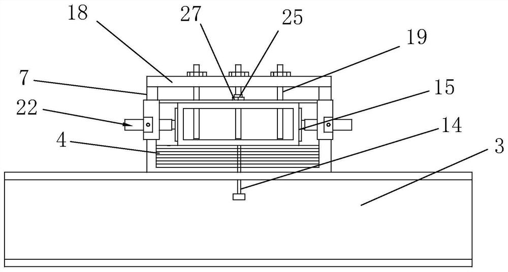
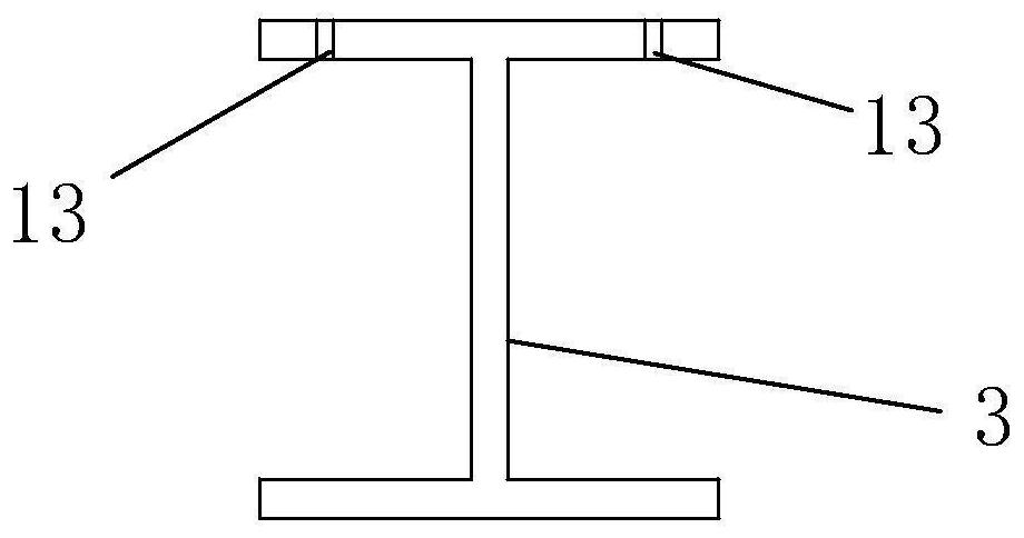
[0056] Such as Figure 1 to Figure 21 As shown, it is a positioning and temporary support stable unloading device for grid hoisting of the present invention, including a support frame 1, a connecting base 2, an H-shaped support beam 3, a spacer 4, a support limit plate 5 and a jack assembly 6, and a connecting base 2 It is welded and fixed on the top surface of the support frame 1, and the H-shaped support beam 3 is welded and fixed on both sides of the top surface of the connecting base 2. The two H-shaped support beams 3 are welded and fixed with a U-shaped support base 7, and the two U-shaped support beams 3 are welded and fixed. The U-shaped draw-in groove 8 of the support base 7 is clamped with pads 8, the support limit plate 5 is arranged between the two U-shaped support bases 7, and the end of the support limit plate 5 rests on the uppermost pad. On the block 4, the two ends of the support limit plate 5 are limited by the limiter 9, the limiter 9 is fixedly connected wi...


PUM


Abstract

The invention discloses a positioning and temporary supporting stable unloading device for net rack hoisting. The positioning and temporary supporting stable unloading device comprises a support frame, connecting bases, H-shaped support beams, cushion blocks, support limiting plates and jack assemblies; the connecting bases are welded and fixed on the top surface of the support frame, the H-shapedsupport beams are welded and fixed at the two side ends of the top surfaces of the connecting bases; U-shaped supporting bases are fixedly welded to the two H-shaped supporting beams; and the cushionblocks are clamped in U-shaped clamping grooves of the two U-shaped supporting bases. The using method comprises the following steps that 1) a butt joint part device is installed; 2) an unloading part device is installed; 3) net rack roof high-altitude butt joint is conducted in a subsection mode; and 4) synchronous unloading operations are carried out. According to the positioning and temporarysupporting stable unloading device for net rack hoisting, by means of the device, the installation accuracy of the net rack roof during segmented hoisting can be guaranteed, meanwhile, step-by-step graded unloading is achieved during unloading, the phenomena that due to an improper unloading scheme, a net rack structure generates large lower deflection, local rod pieces are overstressed, and nodeconnection is damaged and collapsed can be effectively avoided, and the stability and the safety of the whole unloading process are ensured.

Description

technical field [0001] The invention belongs to the technical field of grid structure hoisting, and in particular relates to a positioning, temporary support, stabilizing and unloading device for grid hoisting and a use method thereof. Background technique [0002] At present, grid structures are often used in many airports, stations, gymnasiums and other building structures. This type of structure has the advantages of small space force, light weight, high rigidity, and good seismic performance, but it faces difficulties in construction and installation. The problem of one-time installation in place, the usual solution is to use a temporary support frame for block hoisting. This method involves the unloading of the original structure before the removal of the temporary support frame. Large deflection, overstress of local members, damage of node connections, and even lead to structural collapse in severe cases. Contents of the invention [0003] The purpose of the present...

Claims


Application Information

Patent Timeline
IPC IPC(8): B66C1/10B66C13/08E04G21/14E04G21/18E04G25/02
CPCB66C1/10B66C13/08E04G21/14E04G21/1841E04G25/02
Inventor 王再胜吴晓宇洪靖华李啸天俞科梁董佳铭苏杭
Owner 浙江中南绿建科技集团有限公司
Learn More