
Die-cutting machine for avoiding printing film adhesion and using method thereof

A printing film and die-cutting machine technology, which is applied in metal processing and other directions, can solve the problems of inconvenient adjustment of the cutting knife distance, inconvenient cutting knife quick replacement, and affecting the cutting operation of film materials, so as to avoid adhesion and prevent sticking Attached, easy to adjust and replace the effect

Active Publication Date: 2022-01-04
江西润业环保新材料有限公司
View PDF7 Cites 0 Cited by
  • Summary
  • Abstract
  • Description
  • Claims
  • Application Information

AI Technical Summary

Problems solved by technology

[0005] The purpose of the present invention is to provide a kind of die-cutting machine and using method thereof that avoid printing film adhesion, to solve the existing die-cutting machine on the market that the above-mentioned background technology proposes, and when it is in use, the die-cutting machine on its device When the cutting device is reset after cutting the film, because the finished film after cutting is separated from the film belt, and the film material is relatively soft, it is easy for the film to adhere to the bottom of the die-cutting device, that is, as the die-cutting device rises, it will affect the quality of the film material. Cutting operation, when cutting films of different sizes, it is inconvenient to adjust the distance between the cutting knives, and at the same time, it is inconvenient to quickly replace the cutting knives, which affects the processing efficiency of the die-cutting machine

Method used


Image

  • Die-cutting machine for avoiding printing film adhesion and using method thereof
  • Die-cutting machine for avoiding printing film adhesion and using method thereof
  • Die-cutting machine for avoiding printing film adhesion and using method thereof

Examples


Embodiment Construction

[0037] Based on the embodiments of the present invention, all other embodiments obtained by persons of ordinary skill in the art without making creative efforts belong to the protection scope of the present invention.

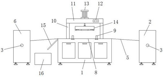
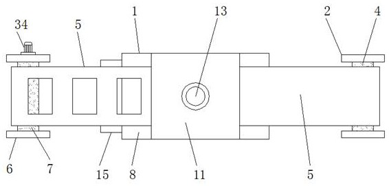
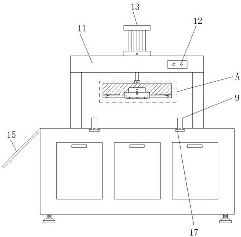
[0038] see Figure 1-9, the present invention provides a technical solution: a die-cutting machine that avoids printing film adhesion, including a die-cutting machine body 1, a feeding frame 2, a rotating shaft 3, a feeding roller 4, a printing film 5, a winding frame 6, Rewinding roller 7, die cutting table 8, limit roller 9, support frame 10, top plate 11, control box 12, cylinder 13, die cutting frame 14, material guide plate 15, material receiving box 16, adjustment chute 17, connection Sleeve 18, compression structure 19, installation chamber 20, air hole 21, compression cavity 22, catheter 23, expansion cavity 24, air bag 25, first limit groove 26, first knife rest 27, first die cutter 28, the first Two die cutters 29, mounting groove 30, second limit gr...


PUM


Abstract

The invention discloses a die-cutting machine for avoiding printing film adhesion and its use method, comprising a die-cutting machine body, a feeding frame, a rotating shaft, a feeding roller, a printing film, a winding frame, a winding roller, and a die-cutting table , a support frame, a top plate, a control box, an air cylinder and a stepping motor, a discharge rack is arranged on one side of the die-cutting machine body, and a discharge roller is arranged on the inside of the discharge rack through a rotating shaft, and the discharge roller is provided with There is a printed film, and the printed film is connected to the winding frame on the other side through the die-cutting table on the die-cutting machine body, and the middle part of the upper surface of the top plate is provided with a cylinder, and the telescopic end of the lower part of the cylinder is connected to the mold through bolts. The connecting sleeve on the top of the cutting frame is connected. The die-cutting machine for avoiding printing film adhesion and its use method, through the improvement of the structure of the existing die-cutting machine, effectively prevent the adhesion of the film finished product on the die-cutting frame, and at the same time, it is convenient for cutting tools on the die-cutting frame Adjustment and replacement of the distance between.

Description

technical field [0001] The invention relates to the technical field of die-cutting machines, in particular to a die-cutting machine for avoiding printing film adhesion and a method for using the same. Background technique [0002] Die-cutting machine is mainly used for the processing of flexible sheet-like materials such as trademarks, decorative labels, paper, self-adhesive stickers and films. It mainly cuts the material through the cutter on the die-cutting machine to form the material into a certain size. finished products, such as comparative document application number: CN201521029469.4, authorized announcement date: 20160511 plastic film die-cutting machine with carrier tape, which mainly sets the hardness of the plastic carrier tape to be greater than the plastic film to be cut, and laminates it with the film It will not be cut through after being cut by the die-cutting device. A plastic carrier tape can cut 6 to 7 rolls of plastic film before it needs to be replaced,...

Claims


Application Information

Patent Timeline
Patent Type & Authority Patents(China)
IPC IPC(8): B26F1/38B26F1/44B26D7/02B26D7/32B26D7/26
CPCB26F1/38B26F1/44B26D7/025B26D7/32B26D7/2628B26D7/2614B26D2007/322
Inventor 朱项龙
Owner 江西润业环保新材料有限公司
Learn More