Anti-falling lifting device

A lifting device and anti-fall technology, which is applied in the direction of lifting device, lifting frame, spring/shock absorber, etc., can solve problems such as safety accidents and falling objects, and achieve the effect of reducing safety accidents.

Active Publication Date: 2021-01-15
CHONGQING TECH & BUSINESS UNIV
View PDF10 Cites 1 Cited by
  • Summary
  • Abstract
  • Description
  • Claims
  • Application Information

AI Technical Summary

Problems solved by technology

[0003] The present invention intends to provide an anti-fall lifting device to solve the problem that the moving objects of the lifting device will fall after the power mechanism fails in the existing lifting device, thus causing safety accidents

Method used


Image

  • Anti-falling lifting device
  • Anti-falling lifting device
  • Anti-falling lifting device

Examples


Embodiment 1

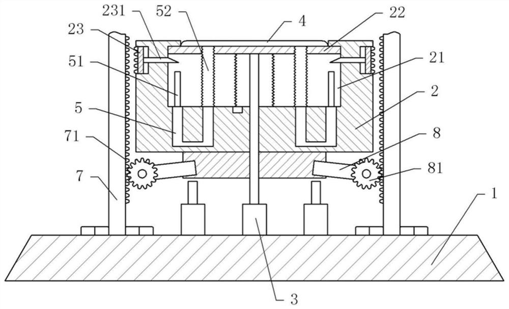
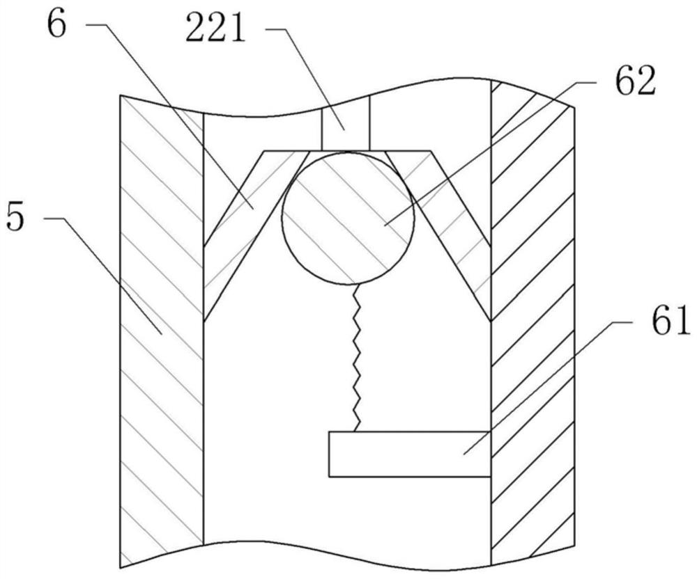
[0037] An anti-fall lifting device, basically as attached figure 1As shown, it includes a base 1, a power structure and a support platform 2 arranged in sequence from bottom to top, and the outer periphery of the support platform 2 is provided with a guardrail; the power mechanism is a pneumatic cylinder 3 fixed on the base 1. The top surface of the support platform 2 is provided with a groove 21 , and the support platform 2 is also provided with two slide grooves respectively communicating with the left and right sides of the groove 21 . The groove 21 is provided with a support plate 22, and both sides of the support plate 22 are fixed with sliders that cooperate with the chute, so that the support plate 22 can slide vertically along the groove 21; A spring is arranged between them, and the two ends of the spring are respectively welded to the bottom of the support plate 22 and the bottom of the groove 21. In this embodiment, the spring here uses a compression spring, and the...

Embodiment 2

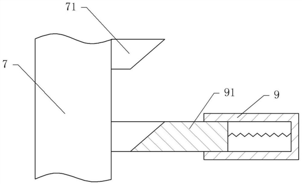
[0051] Embodiment 2 differs from Embodiment 1 only in that, as image 3 As shown, in this embodiment, the anti-slip component includes a sleeve 9 fixed on the end of the support rod 8 away from the mounting block, the sleeve 9 is arranged horizontally, and the end of the sleeve 9 is open towards the vertical rod 7, and the inside of the sleeve 9 is horizontal. A block 91 is slidably connected, and one end of the block 91 located in the sleeve 9 is welded with a spring, and the other end of the spring is welded on the fixed end surface of the sleeve 9 and the support rod 8 . The free end of block 91 is positioned outside sleeve 9, and the free end face of block 91 is inclined downward from top to bottom toward the direction close to vertical bar 7; The direction near the support platform 2 is inclined upward.

[0052] The specific implementation process is as follows:

[0053] When the support platform 2 moves up under the action of the power mechanism, the inclined surface o...


PUM


Abstract

The invention belongs to the technical field of vertical transportation equipment, and discloses an anti-falling lifting device which comprises a base, a power mechanism and a supporting platform sequentially arranged from bottom to top. A guardrail is arranged on the periphery of the supporting platform. The anti-falling lifting device further comprises an anti-falling piece which comprises two vertical rods fixed to the base and a mounting block fixed to the top of the supporting platform. The two vertical rods are located on the two sides of the supporting platform respectively; a pluralityof convex teeth are arranged on the opposite sides of the two vertical rods, and are evenly arranged in the length direction of the vertical rods; two supporting rods are fixed to the mounting block;and anti-skid parts for preventing the supporting platform from falling are arranged at the ends, away from the mounting block, of the supporting rods. The anti-falling lifting device provided by theinvention solves the problem that after a power mechanism of an existing lifting device fails, objects moving by the lifting device fall off, and thus safety accidents occur.

Description

technical field [0001] The invention belongs to the technical field of vertical transportation equipment, and in particular relates to an anti-fall lifting device. Background technique [0002] The lifting device is a hoisting machine that transports objects vertically, and is widely used in production and life. During the use of the lifting device, it is driven by a vertically moving power mechanism to drive the support platform to move vertically, thereby realizing the vertical transportation of the object; when the transported object moves to a suitable position, the power mechanism stops driving, at this time The support platform is only supported by the power mechanism, so the power mechanism is subjected to relatively large pressure for a long time, which will cause the power mechanism to wear and fail. After the power mechanism fails, the support force received by the supporting platform also disappears, and thus it is in a state of extremely fast falling, causing th...

Claims


Application Information

Patent Timeline
IPC IPC(8): B66F7/18B66F7/28F16F15/023
CPCB66F7/18B66F7/28F16F15/0232
Inventor 马斌陈希瑞夏洪均
Owner CHONGQING TECH & BUSINESS UNIV
Why Eureka
Try Eureka