Deodorizing device for cloth processing

A cloth and mounting board technology, which is applied in the direction of processing textile material equipment configuration, processing textile material carrier, spraying/spraying textile material processing, etc., can solve the problems of low work efficiency, troublesome operation, difficult collection, etc., to improve work efficiency, The effect of increasing the range

Inactive Publication Date: 2021-01-15
CHANGLE LIZHI IND DESIGN CO LTD
View PDF0 Cites 4 Cited by
  • Summary
  • Abstract
  • Description
  • Claims
  • Application Information

AI Technical Summary

Problems solved by technology

In order to overcome the disadvantages of troublesome operation, low wo

Method used


Image

  • Deodorizing device for cloth processing
  • Deodorizing device for cloth processing
  • Deodorizing device for cloth processing

Examples


Embodiment 1

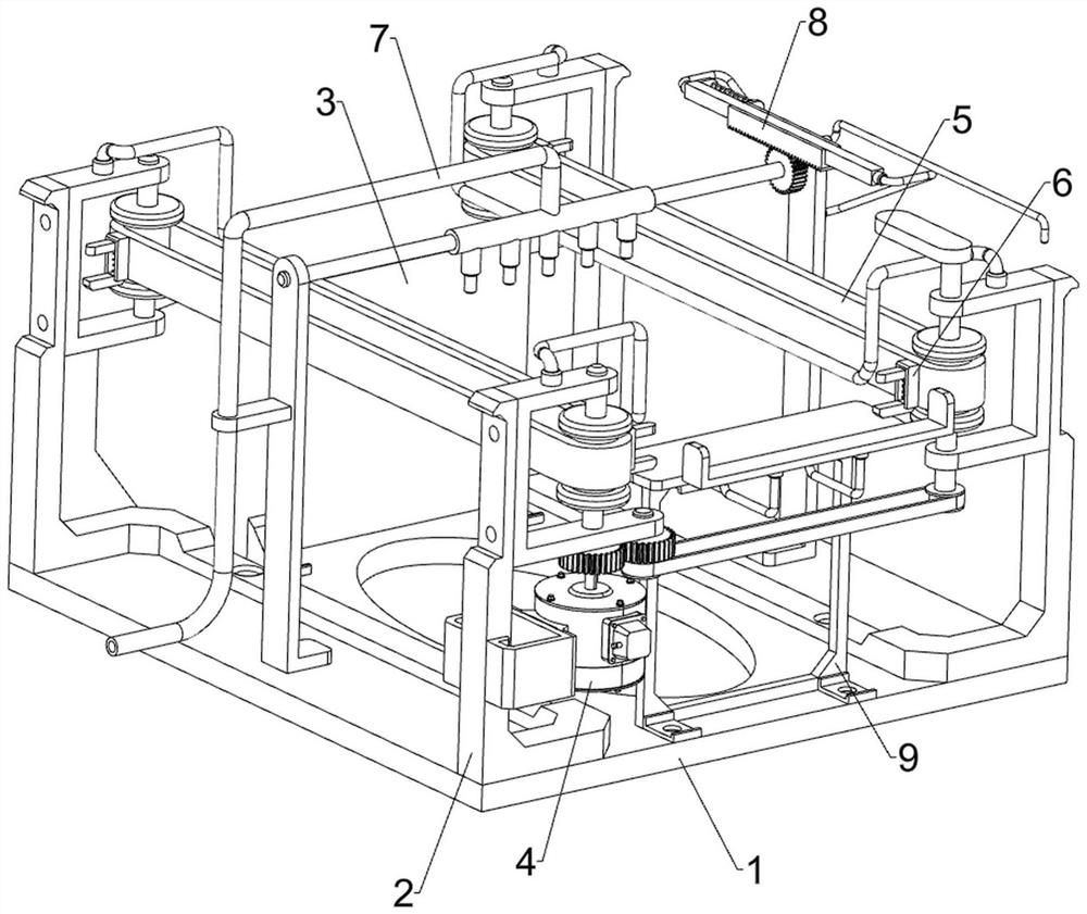
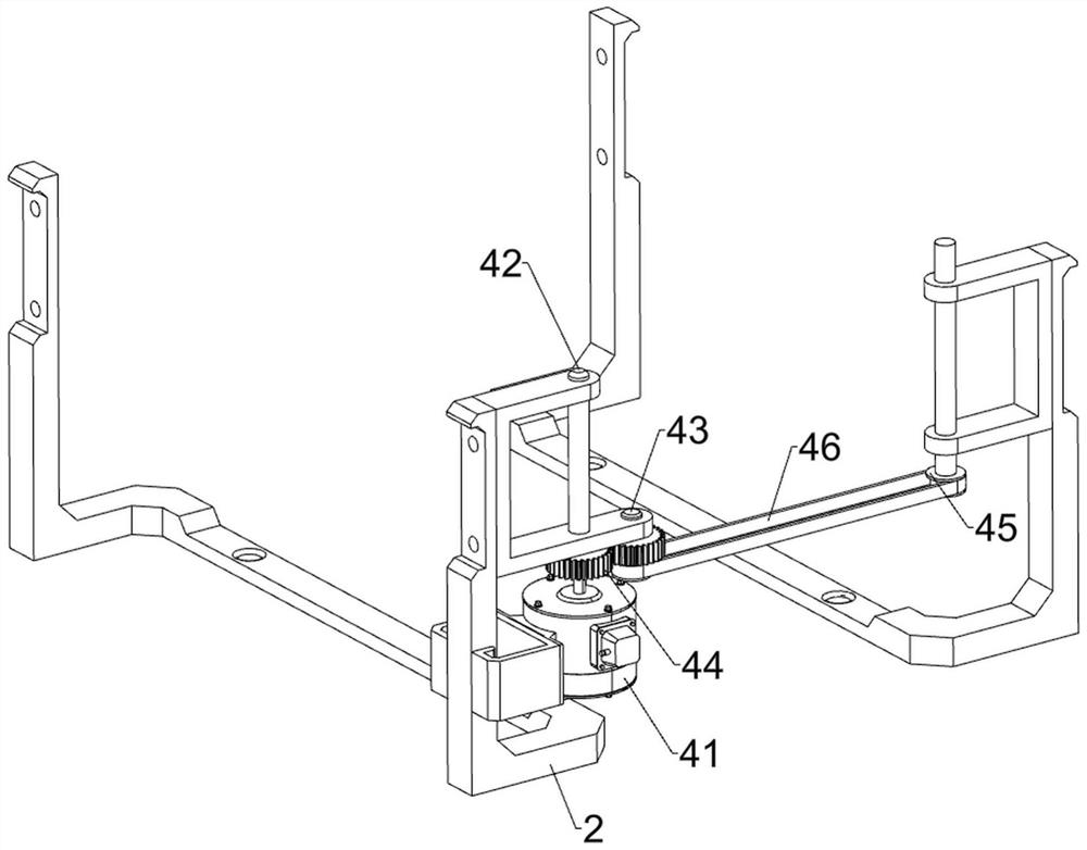
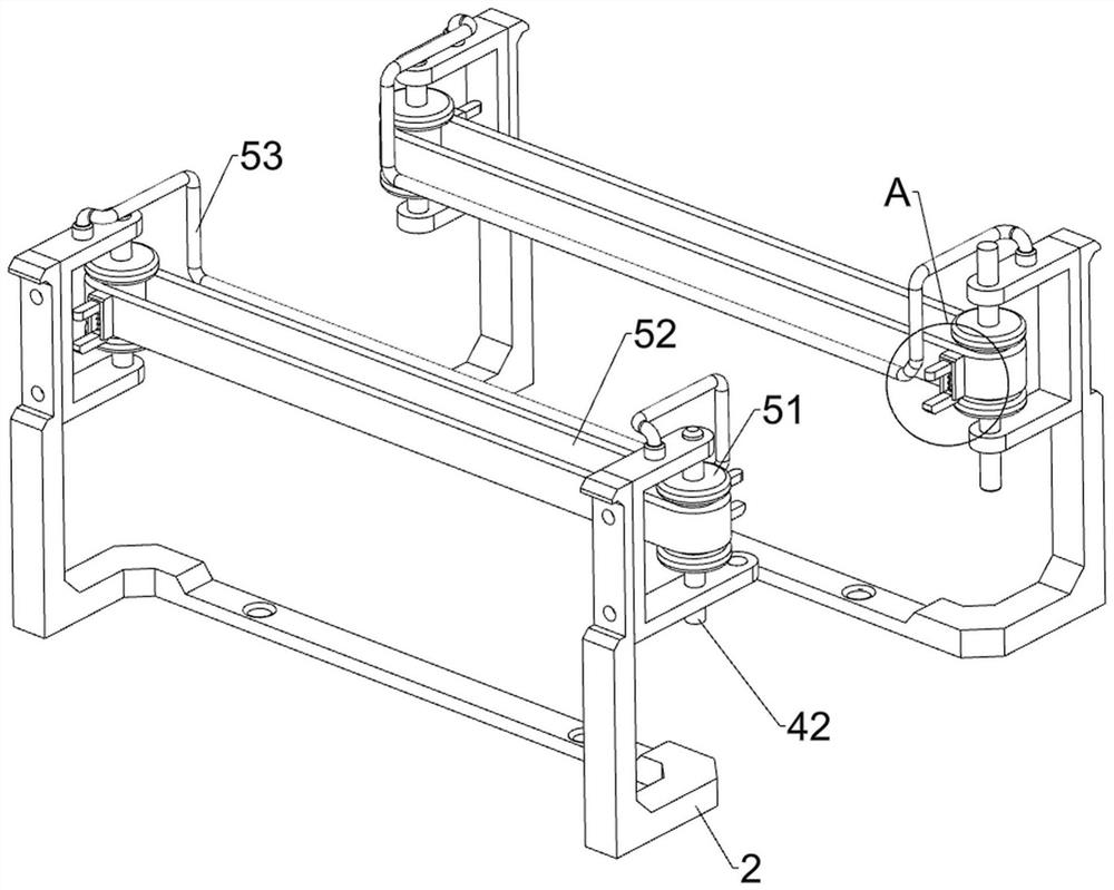
[0027] Such as Figure 1-Figure 5 As shown, a deodorizing device for fabric processing includes a base 1, a support frame 2, a collection frame 3, a driving assembly 4, a conveying assembly 5, a clamping assembly 6 and a spraying assembly 7, and the left and right sides of the base 1 pass through Bolts are fixedly connected with a support frame 2, a collection frame 3 is provided on the rear side of the base 1, a drive assembly 4 is provided between the front sides of the support frame 2, a delivery assembly 5 is provided on the left and right sides of the support frame 2, and a delivery assembly 5 is provided on the delivery assembly 5. A clamping assembly 6 is provided, and a spraying assembly 7 is arranged on the base 1 .

[0028] When it is necessary to deodorize the cloth, first place one end of the cloth between the clamping components 6 on both sides, and then control the driving component 4 to start working, the driving component 4 will drive the conveying component 5 ...

Embodiment 2

[0038] On the basis of Example 1, such asfigure 1 , Image 6 with Figure 7 As shown, a swing assembly 8 is also included, and the swing assembly 8 includes a push plate 81, a second gear 82, a guide plate 83, a rack 84, a second spring 85 and a push rod 86, and the first rotating rod 42 on the right side front The upper part is connected with a push plate 81, the second rotating rod 72 right side key is connected with a second gear 82, the upper part of the mounting plate 71 on the right is connected with a guide plate 83, and the guide plate 83 is slidably provided with a rack 84, the rack 84 Mesh with the second gear 82 , a second spring 85 is connected between the rack 84 and the guide plate 83 , a push rod 86 is connected to the right side of the rack 84 , and the push rod 86 cooperates with the push plate 81 .

[0039] When the first rotating rod 42 on the front right side rotates, it will also drive the push plate 81 to rotate, and when the push plate 81 rotates to con...


PUM


Abstract

The invention discloses a deodorizing device for cloth processing. The deodorizing device comprises a base, supporting frames which are installed on the two sides of the base, a collecting frame whichis mounted on the base, a driving assembly which is mounted between the supporting frames, conveying assemblies which are installed on the two sides of the supporting frames, clamping assemblies which are mounted on the conveying assemblies, and a spraying assembly which is mounted on the base. Cloth can be automatically clamped, the cloth is driven to move to the position below the spraying assembly, and therefore the spraying assembly can spray deodorant to the cloth; cloth subjected to deodorization work can be automatically put into the collecting frame, and a user can conveniently collect and take the cloth subjected to deodorization work; and the spraying assembly swings when deodorizing the cloth, so that the range of spraying a deodorant by spray heads is enlarged, and the workingefficiency of deodorizing the cloth is improved.

Description

technical field [0001] The invention relates to a deodorizing device, in particular to a deodorizing device for fabric processing. Background technique [0002] Cloth is a commonly used material in decorative materials. Including chemical fiber carpets, non-woven wall coverings, linen cloth, nylon cloth, colored tape, flannel and other fabrics. Cloth plays a considerable role in the decorative display, and is often the main force that cannot be ignored in the entire sales space. Extensive use of fabrics for wall decoration, partitions, and background treatment can also form a good commercial space display style. After the fabric is made, it is usually necessary to deodorize the fabric. [0003] At present, when the cloth is deodorized, most of the workers manually spread the cloth, and then spray the deodorant on the placed cloth, so that the deodorization of the cloth is troublesome and the work efficiency is low. It is not easy to collect after deodorization. [0004]...

Claims


Application Information

Patent Timeline
IPC IPC(8): D06B1/02D06B23/04D06B23/20
CPCD06B1/02D06B23/04D06B23/20
Inventor 汪汉坤
Owner CHANGLE LIZHI IND DESIGN CO LTD
Why Eureka
Try Eureka