Protection structure in steel structure building roof plate replacement project

A technology for protective structures and roof panels, applied in building construction, construction, building maintenance, etc., can solve problems such as inconvenience and unfavorable installation and handling of protective devices, and achieve the effects of convenient use, improved installation and handling work, and simple structure.

Inactive Publication Date: 2021-01-15
THE THIRD CONSTR & ENG OF CCFED +1
View PDF11 Cites 0 Cited by
  • Summary
  • Abstract
  • Description
  • Claims
  • Application Information

AI Technical Summary

Problems solved by technology

[0003] However, during the use of the existing protective structure, due to the lack of a good installation mechanism inside, it is extremely inconvenient for external personnel to install and handle it, which is not conducive to the installation and processing of the entire protective device by external personnel

Method used


Image

  • Protection structure in steel structure building roof plate replacement project
  • Protection structure in steel structure building roof plate replacement project
  • Protection structure in steel structure building roof plate replacement project

Examples


Embodiment 1

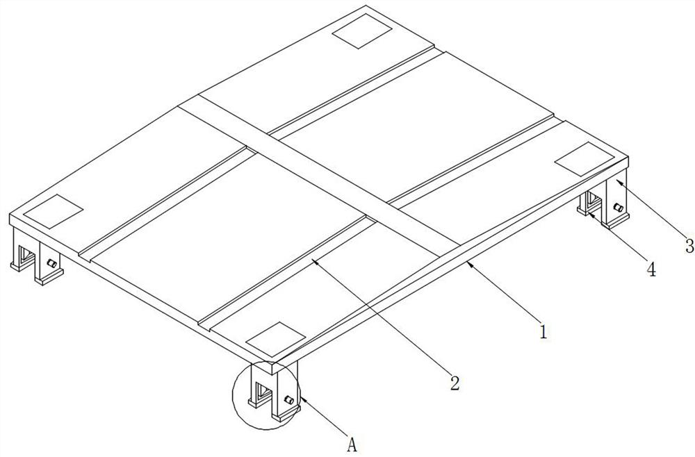
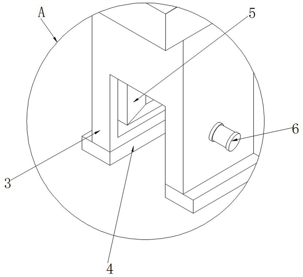
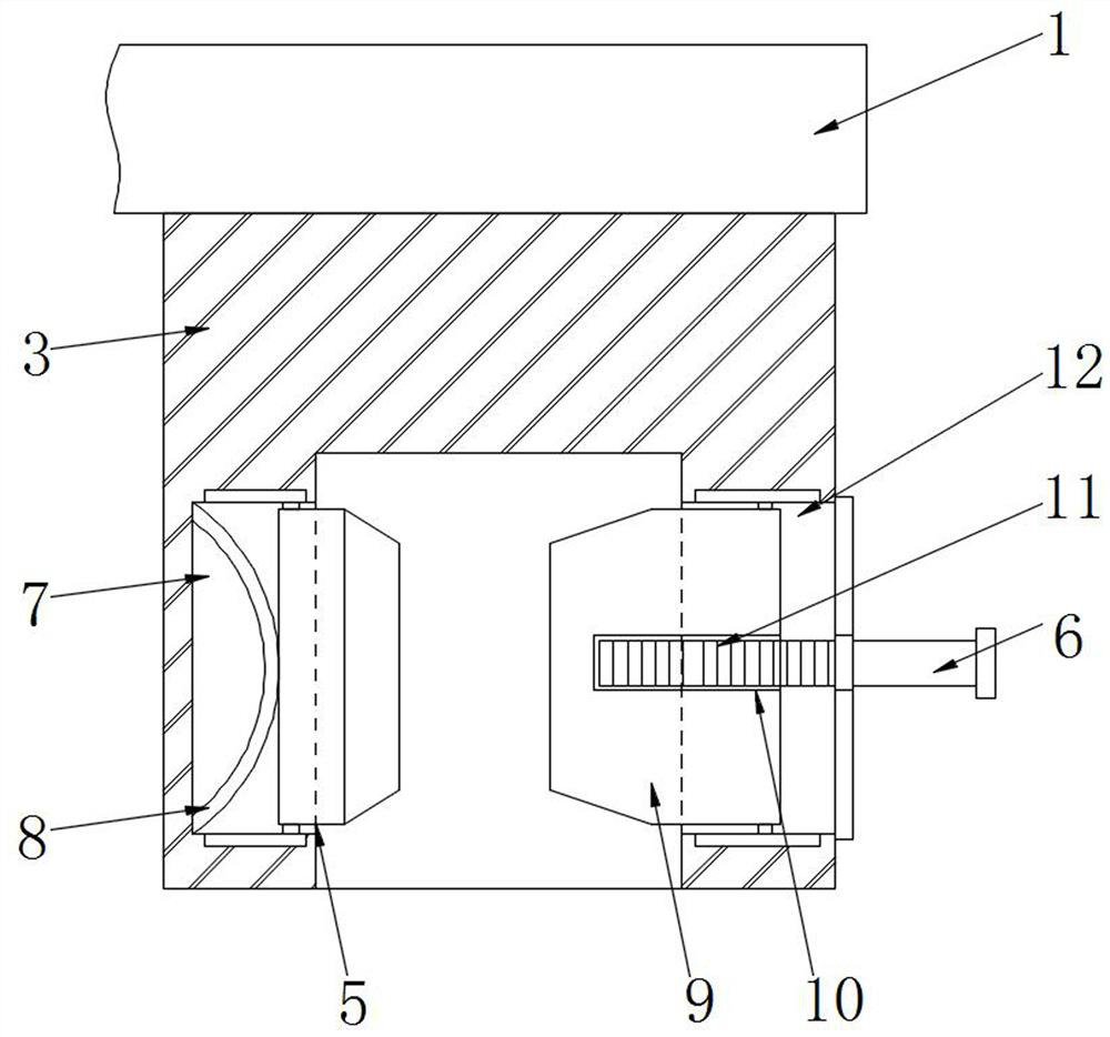
[0026] The main structure of this embodiment, such as Figure 1~3 As shown, by including the upper cover plate 1, side limit blocks 3 are fixedly installed at the four peripheral corners of the lower end of the upper cover plate 1, and several diversion grooves 2 are provided on both sides of the upper end surface of the upper cover plate 1. There is a lock groove 4 inside the limit block 3, and a first movable groove 7 is provided on one side of the inner wall of the lock groove 4, and a collision panel 5 is movably connected inside the first movable groove 7, and the connection between the collision panel 5 and the first movable groove 7 An elastic piece 8 is fixedly connected between them, and the other side of the inner wall of the lock groove 4 is provided with a second movable groove 12 .

[0027] The specific implementation method is that when the upper cover plate 1 is installed, the external personnel can align the side limit block 3 with the external rod body, and af...

Embodiment 2

[0029] In this embodiment, on the basis of the above embodiments, the structure of the second movable groove 12 is further limited, such as image 3 As shown, the inside of the second movable groove 12 is movably connected with a beveled cone plate 9 , and a rotating threaded rod 6 is rotatably connected between the beveled cone plate 9 and the edge limiting block 3 . Other parts of this embodiment are the same as those of the foregoing embodiment, and will not be repeated here.

Embodiment 3

[0031] In this embodiment, on the basis of the foregoing embodiments, the structure of the inclined cone plate 9 is further limited, such as image 3 Therefore, the inside of the inclined cone plate 9 is provided with a built-in through groove 10 for the movement of the rotating threaded rod 6 , and the inner wall of the built-in through groove 10 is provided with a pattern corresponding to the external thread 11 . Other parts of this embodiment are the same as those of the foregoing embodiment, and will not be repeated here.


PUM


Abstract

The invention discloses a protection structure in steel structure building roof plate replacement engineering. The protection structure comprises an upper protection cover plate, wherein edge positionlimiting blocks are fixedly arranged at the peripheral corner positions of the lower end of the upper protection cover plate, a plurality of flow guide grooves are formed in the two sides of the upper end face of the upper protection cover plate, and lock grooves are formed inside the edge position limiting blocks; and bevel cone plates are movably connected into second movable grooves, rotatingthreaded rods are rotationally connected between the bevel cone plates and the edge position limiting blocks, and abutting face plates move towards the interiors of first movable grooves. When the abutting face plates move, elastic sheets are reset after deforming to abut against the abutting face plates, then the rotating threaded rods are directly rotated, in the rotating process of the rotatingthreaded rods, due to the threaded connection between the rotating threaded rods and the bevel cone plates, the rotating threaded rods drive the bevel cone plates to move when rotating, and the bevelcone plates and rod bodies are clamped and fixed so that the clamping and fixing effect on the upper protection cover plate can be directly completed, and external personnel can carry out operation processing conveniently.

Description

technical field [0001] The invention relates to the technical field of building maintenance equipment, in particular to a protective structure in a steel structure building roof panel renewal project. Background technique [0002] At present, the construction time of many high-span buildings in China is relatively long, and the buildings with a long time need to be maintained. In the maintenance process, one of the maintenance procedures is to replace the building roof panels and replace the old ones The roof panel of the banquet roof of a building needs to be replaced, and at the same time, an external protective structure is required to protect it during the replacement process. [0003] However, during the use of the existing protective structure, because there is no better installation mechanism inside, it is extremely inconvenient for external personnel to install and handle it, which is not conducive to the installation and processing of the entire protective device by...

Claims


Application Information

Patent Timeline
Patent Type & Authority Applications(China)
IPC IPC(8): E04G23/03E04G23/02
CPCE04G23/02E04G23/0281
Inventor 周懋辉张艳马俊杨华陈冕
Owner THE THIRD CONSTR & ENG OF CCFED
Why Eureka
Try Eureka