AI technical title is built by Patsnap AI team. It summarizes the technical point description of the patent document.
An assembly and door panel technology, applied in the field of drive mechanism, can solve the problems of poor door sealing, no good solution, damaged acceleration, etc.
Pending Publication Date: 2021-01-15
金湖县微晶控制系统有限公司
View PDF0 Cites 1 Cited by
Summary
Abstract
Description
Claims
Application Information
AI Technical Summary
This helps you quickly interpret patents by identifying the three key elements:
Problems solved by technology
Method used
Benefits of technology
Problems solved by technology
On the one hand, this kind of door lock structure has great potential safety hazards, because when the vehicle is driving, the road surface is bumpy and hollow, and the guide wheel on the door lock will roll back and forth in the guide groove, which will cause the door to be closed. Poor, when running at high speed, the airflow will enter the car from the door gap, affecting the passenger experience; when the vibration is large, the guide wheel may even slide out from the original path in the guide groove, which will cause the door to be broken. Automatic opening, there is a great security risk
On the other hand, in this door lock structure, the power source is fixed on the door frame, and the driving end of the power source is fixed on the guide wheel. When the door is closed or opened, the power applied by the power source is all applied to the guide wheel, and the guide wheel The wheel is the only point of force, and it is easy to cause the guide wheel to be damaged and accelerated due to stress concentration, and because there is only this point of force, when closing or opening the door, the door panels on both sides cannot be guaranteed to be absolutely synchronized, which will cause the two sides to close Or the absolute balance cannot be guaranteed when opening, which may easily cause the door panel to shake
[0004] In order to solve the above-mentioned potential safety hazards, the general solution is to add a cylinder or motor to pull the guide wheel after the door is closed, so that the guide wheel is limited in the guide groove, but this method needs to be used after the door is closed. The larger pulling force limits the position of the guide wheel; and the above-mentioned problem of instability when closing or opening the door has not been solved well, which does not conform to the concept of green environmental protection in today's society
Method used
Image
Click on the blue label to locate the original text in one second.
Reading with bidirectional positioning of images and text.
Examples
Embodiment approach 1
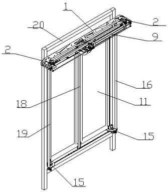
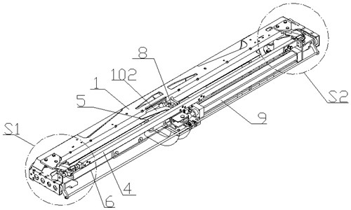
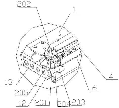
[0073] This embodiment provides a double sliding door assembly, such as Figures 1 to 11 , 17 to 23, mainly by the base 1 fixed on the door frame 20, two sets of shaft-connected drive mechanisms 2, sliding rod 3, pull rod 4, two sliding sleeves 5, wire drawing 6, two wire drawing wheels 7, Guide wheel 8, power source, two door frames 10 and two door panels 11 form.
[0074] Two sets of shaft-connecting drive mechanisms 2 are respectively installed on both ends of the upper part of the base 1. The two sets of shaft-connecting drive mechanisms 2 are mainly composed of a sliding bracket 201, a driving arm 202 and a connecting arm 203. The sliding brackets in the two sets of coupling driving mechanisms 2 201 is fixedly connected through the slide bar 3, and the driving arm 202 is rotatably connected through the pull rod 4, and the slide bar 3 and the pull rod 4 are parallel to each other. In each group of shaft-connecting drive mechanisms 2, the sliding bracket 201 in one group i...
Embodiment approach 2
[0085]This embodiment provides a single sliding door assembly, which has roughly the same structure as the double sliding door assembly in Embodiment 1, and only needs to connect one sliding sleeve, wire drawing and two sliding sleeves in the double sliding door assembly. The first drawing wheel can be removed, and the rest of the structure and working principle are exactly the same, so I won’t repeat them here.
Embodiment approach 3
[0087] This embodiment is a further improvement of Embodiment 1. The main improvement is that in the plug door assembly in Embodiment 1, only the top ends of the door panels 11 on both sides enter the guide groove 102 through the guide wheel 8 for positioning, and the bottom of the door panels 11 There is no positioning mechanism at the end, which will cause the bottom end of the door panel 11 to shake easily when the vehicle runs into a bumpy situation during driving. In this embodiment, a door panel positioning mechanism 15 for positioning the bottom ends of both side door panels 11 is added in the plug door assembly, effectively avoiding the situation that the bottom ends of both side door panels 11 shake and are not stable during driving.
[0088] Specifically, as Figures 12 to 16 , in the plug door assembly in this embodiment, two rotating arms 16 are respectively provided on both sides of the two door panels 11, and the upper and lower ends of the two rotating arms 16 a...
PUM
Abstract
The invention relates to the field of sliding plug doors, and discloses a sliding plug door assembly. The sliding plug door assembly is characterized in that two groups of connecting shaft driving mechanisms are separately arranged at two ends of a base fixed at the upper part of a door frame, are fixedly connected through a sliding rod and are rotationally connected through a pull rod, two sliding sleeves are arranged on the sliding rod in a sleeving mode, and two ends of a drawn wire are connected with the two sliding sleeves after being wound around two wire drawing wheels correspondingly;a guide wheel rotationally connected to one sliding sleeve is limited in a guide groove in the base; a power source of a sliding plug door is fixed on the pull rod, and a driving end of the sliding plug door is fixedly connected with the sliding sleeve connected with the guide wheel; and door plates are fixedly connected to the two sliding sleeves through door carrying frames correspondingly, andthe connecting shaft driving mechanisms are driven by a power source to do reciprocating motion relative to the base. According to the sliding plug door assembly, the force originally concentrated onthe guide wheel is dispersed into the guide wheel and the connecting shaft driving mechanisms on the two sides of the guide wheel, so that the sliding plug door is very stable when opened or closed, the phenomenon that the guide wheel is automatically separated from the guide groove is avoided, and damage to the guide wheel is reduced.
Description
technical field [0001] The invention relates to the field of drive mechanisms, in particular to a sliding door assembly. Background technique [0002] At present, bus doors, subway doors or high-speed rail doors usually use sliding doors. The sliding door has good sealing performance and takes up less space, making the overall model beautiful and generous. The quality of the sliding door lock directly affects the quality of the sliding door. Security and sealing, in order to improve the security of sliding door, the researcher in the field mainly puts the object of research on the structure of sliding door lock. [0003] The currently used plug door lock structure is usually when the door is closed, a guide wheel on the door lock is introduced into the guide groove through a guide groove on the vehicle frame, and the movement of the door lock is restricted by this guide groove, and the door The lock is fixed on the car door, so that the movement of the car door is restricte...
Claims
Application Information
Patent Timeline
Application Date:The date an application was filed.
Publication Date:The date a patent or application was officially published.
First Publication Date:The earliest publication date of a patent with the same application number.
Issue Date:Publication date of the patent grant document.
PCT Entry Date:The Entry date of PCT National Phase.
Estimated Expiry Date:The statutory expiry date of a patent right according to the Patent Law, and it is the longest term of protection that the patent right can achieve without the termination of the patent right due to other reasons(Term extension factor has been taken into account ).
Invalid Date:Actual expiry date is based on effective date or publication date of legal transaction data of invalid patent.

