
Drill rod centering guide for oil-gas drilling

A technology for oil and gas drilling and centralizers, which is applied in the direction of drill pipes, drilling equipment, drill pipes, etc. It can solve the problems of inducing downhole accidents and reducing the risk of stuck pipe in the mud bag of the centralizer, and achieve the effect of reducing the risk of stuck pipe

Inactive Publication Date: 2021-01-15
熊朝柱
View PDF0 Cites 0 Cited by
  • Summary
  • Abstract
  • Description
  • Claims
  • Application Information

AI Technical Summary

Problems solved by technology

[0004] The purpose of the present invention is to provide a drill pipe centralizer for oil and gas drilling, to solve the problem in the prior art that the drill pipe centralizer is prone to mud bagging and then induce downhole accidents, and to provide the drill pipe centralizer with a self-blocking function and reduce centralization Purpose of mud bag sticking risk

Method used


Image

  • Drill rod centering guide for oil-gas drilling
  • Drill rod centering guide for oil-gas drilling
  • Drill rod centering guide for oil-gas drilling

Examples


Embodiment 1

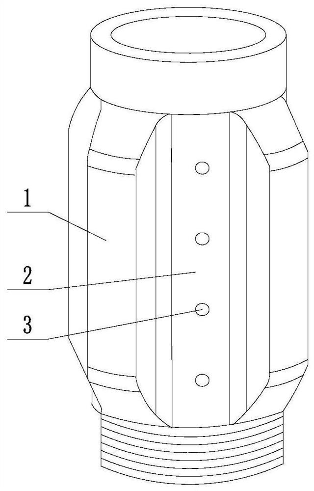
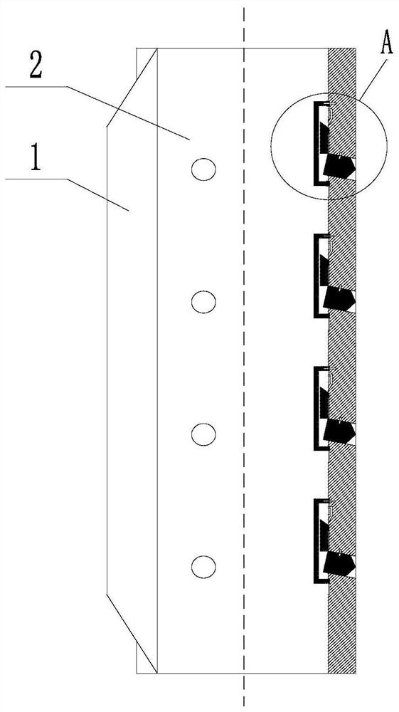
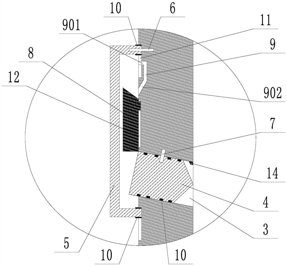
[0038] Such as Figure 1 to Figure 5 The drill pipe centralizer shown includes several centralizing wings 1 and an upper backflow channel 2 between two adjacent centralizing wings 1, and is characterized in that several through holes 3 are provided on the upper backflow channel 2, so that The through hole 3 is sealed with a tapered part 4, the tapered end of the tapered part 4 faces the outside of the through hole 3, and the tapered part 4 is connected with the wall of the through hole 3 through the first shear pin 7; It includes a sliding sleeve 5 corresponding to the through holes 3 one by one, the sliding sleeve 5 is sealed and connected to the inner wall of the centralizer, and the sliding sleeve 5 and the centralizer are connected by a second shear pin 6, and the first The shear stress of the shear pin 7 is less than the shear stress of the second shear pin 6; each sliding sleeve 5 is provided with a sliding push block 8 and a pressurized flow channel 9, and the inlet sec...

Embodiment 2

[0043] Such as Figure 1 to Figure 5 For the drill pipe centralizer shown, on the basis of Embodiment 1, the through hole 3 is inclined downward from the inside to the outside, the outer diameter of the conical part 4 is less than or equal to the inner diameter of the through hole 3, and the conical part 4 and the through hole 3. Several O-rings 10 are dynamically sealed between the hole walls. The bottom surface of the cone 4 is perpendicular to the axis of the through hole 3. When the first shear pin 7 is connected, the top end of the bottom surface of the cone 4 is flush with the inner wall of the centralizer, and the cone 4 supports the slide from below. Push block 8. The inner wall of the centralizer defines a first chute 11 for the sliding of the sliding sleeve 5 , and the sliding sleeve 5 and the first chute 11 are in dynamic and sealing cooperation. The inner wall of the centralizer defines a second sliding slot 12 for the sliding push block 8 to slide. The outlet s...


PUM


Abstract

The invention discloses a drill rod centering guide for oil-gas drilling. The centering guide comprises a centralizing wing and an upward flow returning channel; a plurality of through holes are formed in the upward flow returning channel; conical parts are arranged in the through holes in a sealing fit; the pointed cone ends of the conical parts face the outer sides of the through holes; and theconical parts are connected with the hole walls of the through holes through first shear pins. The centering guide further comprises sliding sleeves in one-to-one correspondence with the through holes, and the sliding sleeves are connected with a centering guide body through second shear pins; a sliding push block and a pressurizing flow channel are arranged in each sliding sleeve; an inlet section and an outlet section of each pressurizing flow channel are both formed in the inner wall of the centering guide body; when the sliding sleeves descend to a stroke low position, the tops of slidingsleeves are located between the inlet sections and the outlet sections of the corresponding pressurizing flow channels; and the sliding push blocks apply pressure to the conical parts in the descending process to shear off the first shear pins. The drill rod centering guide for oil-gas drilling solves the problem that in the prior art, a drill rod centering guide is prone to balling, and consequently downhole accidents are induced, and the purposes of providing a self-unblocking function for the drill rod centering guide and reducing the risk that a drill is stuck by the balling of the centering guide are achieved.

Description

technical field [0001] The invention relates to the field of oil and gas drilling, in particular to a drill pipe centralizer for oil and gas drilling. Background technique [0002] Drilling engineering is an important intermediate link in the process of oil and gas extraction, and drill pipe is one of the essential tools. The drill pipe centralizer is a very important drilling tool in the downhole drilling tool assembly. Its main functions are 3: (1) To straighten the bottom hole assembly, improve the centering degree of the bottom hole assembly in the wellbore, reduce the pressure difference sticking, The risk of stuck pipe sticking; (2) As part of the pendulum drilling tool assembly in vertical wells, it can prevent deviation and straighten and improve the verticality of the wellbore; (3) In directional wells and even horizontal wells using screw drilling tools During operation, as a lever fulcrum for directional deflection, it plays a key role in controlling the wellbore...

Claims


Application Information

Patent Timeline
Patent Type & Authority Applications(China)
IPC IPC(8): E21B17/10E21B21/00
CPCE21B17/1078E21B21/00
Inventor 不公告发明人
Owner 熊朝柱
Learn More