Drill rod centralizer

A technology for centralizers and drill pipes, applied in the direction of drill pipes, drill pipes, drilling equipment, etc., can solve the problems of induced downhole accidents, etc., and achieve the effect of increasing the overall length and large stroke space

Inactive Publication Date: 2021-01-15
熊朝柱
View PDF0 Cites 0 Cited by
  • Summary
  • Abstract
  • Description
  • Claims
  • Application Information

AI Technical Summary

Problems solved by technology

[0004] The purpose of the present invention is to provide a drill pipe centralizer to solve the problem in the prior art that the drill pipe centralizer is prone to mud bagging

Method used


Image

  • Drill rod centralizer
  • Drill rod centralizer
  • Drill rod centralizer

Examples


Embodiment 1

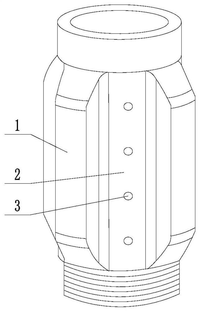
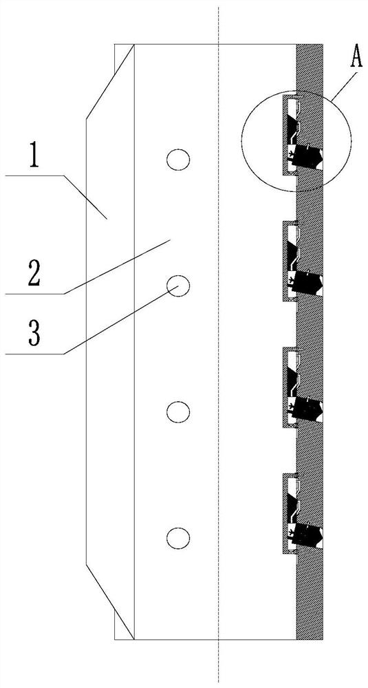
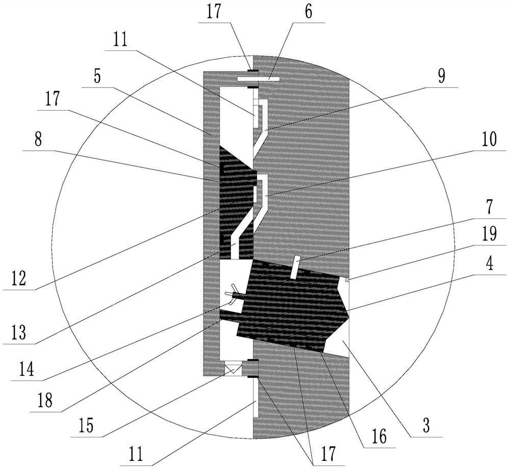
[0044] Such as Figure 1 to Figure 5 A drill pipe centralizer shown includes several centralizing wings 1, an upper backflow channel 2 located between two adjacent centralizing wings 1, and several through-holes 3 are provided on the upper backflow channel 2, and the through-holes 3 The hole 3 is sealed with a tapered piece 4, the tapered end of the tapered piece 4 faces the outside of the through hole 3, and the tapered piece 4 is connected to the wall of the through hole 3 through the first shear pin 7; The through holes 3 correspond to the sliding sleeves 5 one by one. The sliding sleeves 5 are sealed and connected to the inner wall of the centralizer. The bottom of the sliding sleeves 5 is provided with a one-way valve 15. The direction of the one-way valve 15 is from the inside of the sliding sleeve to the outside of the sliding sleeve. Conduction, that is, conduction from top to bottom in the figure, and the connection between the sliding sleeve 5 and the centralizer is ...

Embodiment 2

[0057] Such as Figure 1 to Figure 5 In the shown drill pipe centralizer, on the basis of Embodiment 1, the through hole 3 is inclined downward from the inside to the outside, and the axis of the tapered part 4 is collinear with the axis of the through hole 3 . Cooperate by bearing 16 between described conical part 4 and through hole 3, the outer ring of described bearing 16 is connected with through hole 3 hole wall by first shear pin 7, the inner ring of described bearing 16 and conical part 4 Rotational connection; several sealing rings 17 are sheathed on the outer ring of the bearing 16 . A protruding portion 18 is provided on the side of the conical member 4 away from the pointed conical end, and when the first shear pin 7 is kept connected, the protruding portion 18 is in contact with the inner wall of the sliding sleeve 5 . The sliding push block 8 is in dynamic sealing cooperation with the inner wall of the sliding sleeve 5, and the sliding pushing block 8 divides the...


PUM


Abstract

The invention discloses a drill rod centralizer. The drill rod centralizer comprises a centralizing wing, an upward flow channel and a through hole, wherein a conical part is arranged in the through hole in a sealing fit mode, and the conical part is connected with the hole wall of the through hole through a first shear pin; the drill rod centralizer further comprises a sliding sleeve, the slidingsleeve is connected to the inner wall of the centralizer in a sealing mode, a one-way valve is arranged at the bottom of the sliding sleeve, and the sliding sleeve is connected with the centralizer through a second shear pin; a first pressurizing flow channel and a second pressurizing flow channel are formed in the inner wall of the centralizer, and a third pressurizing flow channel is further formed in a sliding push block; when the sliding sleeve moves downwards to a low stroke position, the upper end of the first pressurizing flow channel is located outside the sliding sleeve; when the sliding push block moves downwards to the low stroke position, the second pressurizing flow channel communicates with the third pressurizing flow channel; and a plurality of spiral blades are further arranged at the end, away from the pointed cone end, of the conical part. The drill rod centralizer is used for solving the problem that in the prior art, a drill rod centralizer is prone to mud drum andthen underground accidents are induced, and the purposes of providing a self-unblocking function for the drill rod centralizer and reducing the risk of jamming of a drill by the mud drum of the centralizer are achieved.

Description

technical field [0001] The invention relates to the field of oil and gas drilling, in particular to a drill pipe centralizer. Background technique [0002] Drilling engineering is an important intermediate link in the process of oil and gas extraction, and drill pipe is one of the essential tools. The drill pipe centralizer is a very important drilling tool in the downhole drilling tool assembly. Its main functions are: (1) Centralize the bottom hole assembly, improve the centering degree of the bottom hole assembly in the wellbore, and reduce the pressure difference and sticking of the drill pipe , the risk of sticking and stuck pipe; (2) as a part of the pendulum drilling tool assembly in the vertical well drilling operation, it plays the purpose of preventing deviation and straightening and improving the verticality of the wellbore; In the process of downhole or even horizontal well operation, as a lever fulcrum for directional deflection, it plays a key role in controll...

Claims


Application Information

Patent Timeline
IPC IPC(8): E21B17/10E21B21/00
CPCE21B17/1078E21B21/00
Inventor 不公告发明人
Owner 熊朝柱
Why Eureka
Try Eureka