Coupler facilitating limitation of adjustable range

A coupling and adjustable technology, applied in the direction of couplings, elastic couplings, mechanical equipment, etc., can solve problems such as inconvenient installation, shaft damage, secondary shaft damage, etc., to avoid slippage and reduce damage , easy to fix the effect

Active Publication Date: 2021-01-15
YANTAI ENG & TECH COLLEGE YANTAI TECHNICIAN INST
View PDF7 Cites 1 Cited by
  • Summary
  • Abstract
  • Description
  • Claims
  • Application Information

AI Technical Summary

Problems solved by technology

[0002] With the current development of science and technology, the industry has begun to use couplings to connect two shafts (drive shaft and driven shaft) in different mechanisms to make them rotate together to transmit torque mechanical parts. In high-speed and heavy-duty power transmission Among them, some couplings also have the function of buffering, damping and improving the dynamic performance of the shaft system. The coupling is composed of two halves, which are respectively connected with the driving shaft and the driven shaft. However, during the use of some couplings, sometimes a coupling made of one material cannot meet the conditions of use, including the fact that there is a centrifugal difference between the main shaft and the secondary shaft during use. It is necessary to use a coupling that can produce centrifugal difference, but because this coupling cannot ensure that the centrifugal difference between the main shaft and the secondary shaft is within a certain range during use, it is easy to cause damage to the secondary shaft, and in the During the installation process, due to the contact between the coupling and the shaft body for installation, and the need to repeatedly adjust the position of the device during installation, it is very inconvenient during installation, and it is relatively easy to cause damage to the shaft body

Method used


Image

  • Coupler facilitating limitation of adjustable range
  • Coupler facilitating limitation of adjustable range
  • Coupler facilitating limitation of adjustable range

Examples


Embodiment Construction

[0025] The following will clearly and completely describe the technical solutions in the embodiments of the present invention with reference to the accompanying drawings in the embodiments of the present invention. Obviously, the described embodiments are only some of the embodiments of the present invention, not all of them. Based on the embodiments of the present invention, all other embodiments obtained by persons of ordinary skill in the art without making creative efforts belong to the protection scope of the present invention.

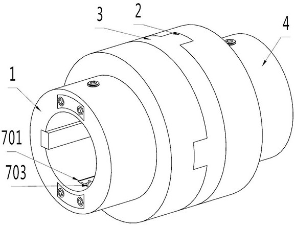
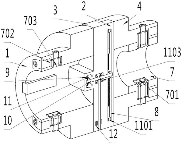
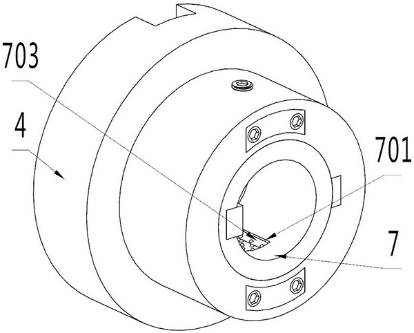
[0026] see Figure 1-7 , the present invention provides a technical solution: a coupling that is convenient to limit the adjustable range, including a main coupling body 1, a connecting block 2, a center plate 3, a secondary coupling body 4, and a limiting groove 5 , buckle 6, shaft locking ring 7, built-in groove 701, moving block 702, positioning block 703, chute 8, slider 9, main shaft 10, moving bar 11, limit block 1101, cylindrical spur gear...


PUM


Abstract

The invention discloses a coupler facilitating limitation of an adjustable range. The coupler comprises a main coupler body, a connecting block, a center plate, a cylindrical pin and a reset spring, and the connecting block is clamped on the outer surface of the main coupler body; the center plate and a secondary coupler body are fixedly installed on the outer surface of the connecting block; anda limiting groove is formed in the outer surface of the secondary coupler body, and a sliding groove is formed in the inner surface of the connecting block. According to the coupler facilitating limitation of the adjustable range, an adjustable shaft body locking ring is arranged, and is easy to install in the coupler through a buckle installed on the outer surface of the shaft body locking ring,and both the inner surface of the shaft body locking ring and the inner surface of the coupler are provided with built-in grooves; movable blocks can be installed on the inner surfaces of the built-ingrooves slidably, and locating blocks with locking functions are fixedly installed on the outer surfaces of the movable blocks; and meanwhile, the outer surfaces of the locating blocks are provided with circular protruding structures facilitating extrusion, locking and fixation of the shaft body.

Description

technical field [0001] The invention relates to the technical field of shaft couplings, in particular to a shaft coupling for conveniently limiting an adjustable range. Background technique [0002] With the current development of science and technology, the industry has begun to use couplings to connect two shafts (drive shaft and driven shaft) in different mechanisms to make them rotate together to transmit torque mechanical parts. In high-speed and heavy-duty power transmission Among them, some couplings also have the function of buffering, damping and improving the dynamic performance of the shaft system. The coupling is composed of two halves, which are respectively connected with the driving shaft and the driven shaft. However, during the use of some couplings, sometimes a coupling made of one material cannot meet the conditions of use, including the fact that there is a centrifugal difference between the main shaft and the secondary shaft during use. It is necessary ...

Claims


Application Information

Patent Timeline
IPC IPC(8): F16D3/26
CPCF16D3/265
Inventor 宋教华李刚宋雪妮苏丹娅方少军
Owner YANTAI ENG & TECH COLLEGE YANTAI TECHNICIAN INST
Why Eureka
Try Eureka