
Method for reducing water hammer effect, liquid flow shutoff system and water conservancy project

A technology of water hammer effect and liquid flow, applied in water conservancy projects, water conservancy engineering equipment, pipes/pipe joints/fittings, etc., can solve problems such as time delay, pipeline damage, large gate damage, etc., and achieve low cost, time saving, damage reduction effect

Inactive Publication Date: 2021-01-15
杭州王之新创信息技术研究有限公司
View PDF6 Cites 3 Cited by
  • Summary
  • Abstract
  • Description
  • Claims
  • Application Information

AI Technical Summary

Problems solved by technology

[0003] The water hammer effect will not only cause damage to the pipeline, but also cause great damage to the sluice. In order to overcome the water hammer effect, a lot of research has been carried out in the prior art, but the existing technology mainly relies on reducing the closing speed of the sluice to reduce the water hammer effect. Very time-consuming, there is room for improvement

Method used


Image

  • Method for reducing water hammer effect, liquid flow shutoff system and water conservancy project
  • Method for reducing water hammer effect, liquid flow shutoff system and water conservancy project
  • Method for reducing water hammer effect, liquid flow shutoff system and water conservancy project

Examples


Embodiment 1

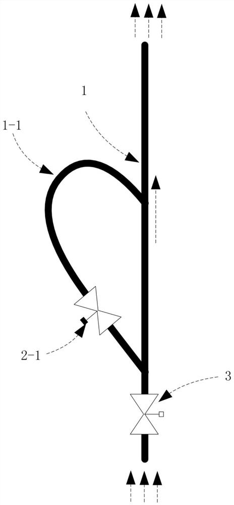
[0031] Embodiment 1, as figure 1 As shown, a method for reducing the water hammer effect is characterized in that when designing the fluid channel, the bypass channel (1-1) of the Tesla valve is integrated on both sides of the main channel (1), and the fluid direction of the fluid channel For the high-resistance direction of the Tesla valve structure; design the bypass valve (2-1) on the bypass channel (1-1), design the main valve (3) on the main channel (1); design the main channel (1-1) ) when working, the main valve (3) opens the bypass valve (2-1) and closes; when the main channel (1) needs to be shut off, first close the bypass valve (2-1), so that the main channel (1) and the bypass water channel (1-1) together constitute a Tesla valve, which reduces the flow rate of the fluid channel and then closes the main valve (3).

[0032] The bypass waterway (1-1) is a pipe or a tank.

[0033] Road (1) is a pipe or a groove.

[0034] The bypass valve (2-1) is a pipeline valve o...

Embodiment 2

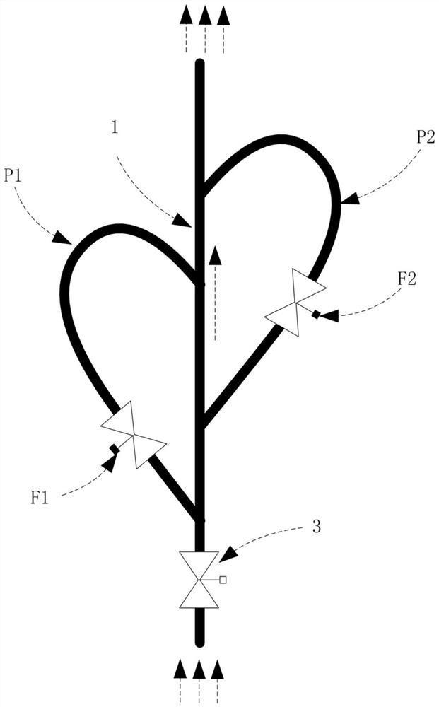
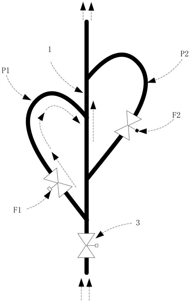
[0036] Embodiment 2, as Figure 2-5 As shown, the number of bypass channels (1-1) is 2, the first bypass valve (F1) is located in the fluid path of the first bypass channel (P1), and the second bypass valve (F2) is located in the second bypass channel (P2) on the fluid path.

[0037] implementation, 3, such as Figure 6 The number of bypass waterways (1-1) shown is greater than two, and each bypass waterway (1-1) has a bypass valve (2-1).


PUM


Abstract

The invention relates to the field of fluid mechanics. A method for reducing the water hammer effect comprises the steps that bypass water channels (1-1) of a Tesla valve are integrated to two sides of a main channel (1), and the fluid direction of a fluid channel is the high-resistance direction of a Tesla valve structure; a bypass valve (2-1) is designed on the bypass water channel (1-1), and amain valve (3) is designed on the main channel (1); when the main channel (1) works, the main valve (3) is opened and the bypass valve (2-1) is closed; and when the main channel (1) needs to be closed, the bypass valve (2-1) is closed firstly, the flow speed of the fluid channel is reduced, and then the main valve (3) is closed. A liquid flow shutoff system comprises the main channel (1), the bypass water channel (1-1), the main valve (3) and the bypass valve (2-1). In a water conservancy project, the method for reducing the water hammer effect is adopted to reduce the water hammer effect. According to the method, the system and the water conservancy project, the structure is simple, the cost is low, the time can be saved, the loss is reduced, the service lifetime is long, the promotion iseasy, and a new technical thought is provided.

Description

technical field [0001] The invention relates to the field of fluid mechanics, and specifically relates to a method for reducing the water hammer effect, a liquid flow shut-off system, and a water conservancy project. Background technique [0002] The water hammer effect means that inside the water pipe, the inner wall of the pipe is smooth and the water flows freely. When an open valve is suddenly closed, the flow of water creates a pressure on the valve and pipe wall. Due to the smooth pipe wall, the subsequent water flow under the action of inertia quickly reaches the maximum water pressure. This is the water hammer effect in hydraulics, that is, positive water hammer. On the contrary, after the closed valve is suddenly opened, it will also produce water hammer, which is called negative water hammer. It also has a certain water pressure, but it is not as big as the former. [0003] The water hammer effect will not only cause damage to the pipeline, but also cause great d...

Claims


Application Information

Patent Timeline
IPC IPC(8): F16L55/045F16L55/055E02B1/00
CPCE02B1/00F16L55/045F16L55/055
Inventor 彭亚林
Owner 杭州王之新创信息技术研究有限公司
Learn More