Rotating disc type mold overturning mechanism

A mold-turning mechanism and turntable technology, which is applied to conveyor objects, transportation and packaging, coating, etc., can solve the problems of large equipment renovation costs and increased travel, and achieve reduced equipment costs, fast and reliable action, and movement saving. effect of time

Pending Publication Date: 2021-01-19
SUZHOU GUANGYUE MICRO NANO TECH CO LTD
View PDF0 Cites 0 Cited by
  • Summary
  • Abstract
  • Description
  • Claims
  • Application Information

AI Technical Summary

Problems solved by technology

With the increase of the number of stations, the stroke of the traveling mechanism will

Method used


Image

  • Rotating disc type mold overturning mechanism
  • Rotating disc type mold overturning mechanism

Examples


Embodiment Construction

[0027] Below in conjunction with specific embodiment, content of the present invention is described in further detail:

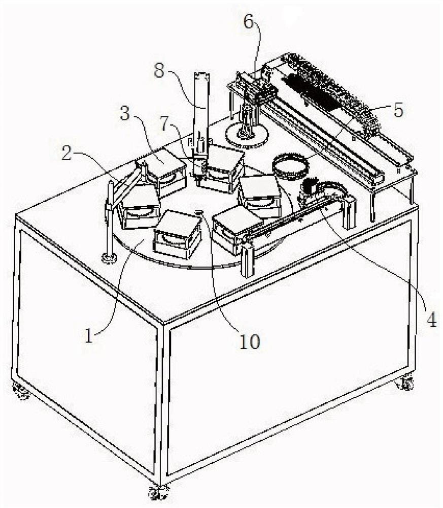
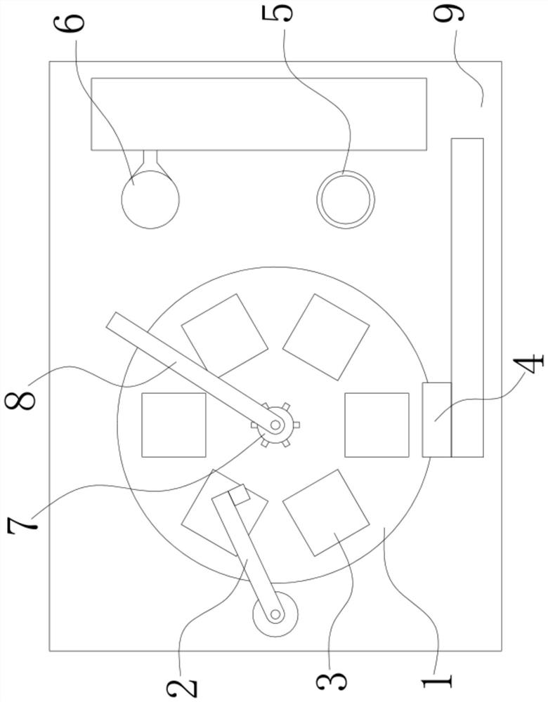
[0028] In order to achieve the purpose of the present invention, a turntable type mold turning mechanism includes: a turntable station, including a turntable 1 arranged horizontally, and several stations 3 are arranged in an annular array on the upper surface of the turntable 1; a mold taking ring mechanism 6 is arranged horizontally On one side of the turntable 1, the mold taking ring mechanism 6 has at least a linear reciprocating translation degree of freedom along its own length; The length direction of the mold-taking mechanism 4 and the length direction of the mold-taking ring mechanism 6 are perpendicular to each other, and the motion track of the mold-taking ring mechanism 6 intersects with the motion track of the mold-taking mechanism 4; Directly above, the self-axis of the driven pipe 7 is vertically arranged, and the driven pipe 7 has a degree of ...


PUM


Abstract

The invention discloses a rotating disc type mold overturning mechanism. The mechanism comprises a rotating disc station, a mold ring taking mechanism, a mold taking mechanism and a driven pipe, wherein the rotating disc station comprises a rotating disc arranged horizontally, the upper surface of the rotating disc is provided with a plurality of station bodies in an annular array mode, the mold ring taking mechanism is horizontally arranged on one side of the rotating disc and at least has a linear reciprocating translation freedom degree in the length direction of the mold ring taking mechanism, the mold taking mechanism is horizontally arranged on one side of the rotating disc and at least has a linear reciprocating translation freedom degree in the length direction of the mold taking mechanism, the length direction of the mold taking mechanism is perpendicular to the length direction of the mold ring taking mechanism, a motion trail of the mold ring taking mechanism intersects witha motion trail of the mold taking mechanism, the driven pipe is arranged over a circle center of the rotating disc, the axis of the driven pipe is vertically arranged, the driven pipe has a rotatingfreedom degree around the axis of the driven pipe, a plurality of through pipes extending in the radial direction are arranged on the driven pipe, and the number of the through pipes is equal to the number of the station bodies. By adopting the mechanism, the cost is low, the action efficiency of each mechanism is high, and a pipeline is not easy to twist due to rotary motion.

Description

technical field [0001] The invention relates to the field of micro-nano imprinting equipment, in particular to a turntable type mold turning mechanism. Background technique [0002] In the existing field of micro-nano imprinting, templates within a certain period need to be moved into and out of the mold, which is generally achieved by some walking mechanisms. In order to improve the embossing efficiency, the embossing stations are generally several in a rectangular array, which determines that the traveling mechanism must at least have the freedom of horizontal and vertical translation in the horizontal plane. The walking track of the traveling mechanism to enter or exit the mold is generally at least a two-fold or even three-fold line, which is not conducive to the further improvement of efficiency. As the number of stations increases, the stroke of the traveling mechanism also increases accordingly, and the cost of equipment transformation is also high. Contents of the...

Claims


Application Information

Patent Timeline
IPC IPC(8): B65G47/80B65G47/91B05C5/02B05C11/10
CPCB05C5/02B05C11/10B65G47/80B65G47/91
Inventor 史晓华吏国宝
Owner SUZHOU GUANGYUE MICRO NANO TECH CO LTD
Why Eureka
Try Eureka