
Valve device with adjustable compression damping

A valve device and damping technology, which is applied in the direction of vibration suppression adjustment, shock absorber, shock absorber, etc., can solve the problems of compression valve dependence, low system reliability, and high product cost, so as to reduce high-speed damping force and reduce vehicle Effect of weight and cost reduction

Pending Publication Date: 2021-01-19
NANYANG XIJIAN AUTOMOBILE SHOCK ABSORBER +2
View PDF0 Cites 2 Cited by
  • Summary
  • Abstract
  • Description
  • Claims
  • Application Information

AI Technical Summary

Problems solved by technology

[0004] The purpose of the present invention is to overcome the deficiencies in the prior art, solve or at least alleviate the problems of traditional compression valves relying on electronic control systems and sensors, high product costs, and low system reliability, and provide a valve device with adjustable compression damping

Method used


Image

  • Valve device with adjustable compression damping
  • Valve device with adjustable compression damping
  • Valve device with adjustable compression damping

Examples


Embodiment 1

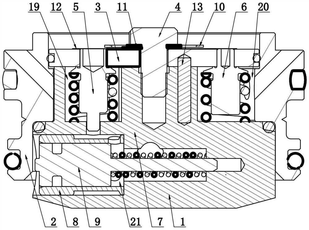
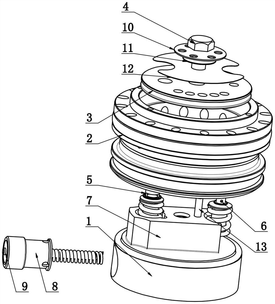
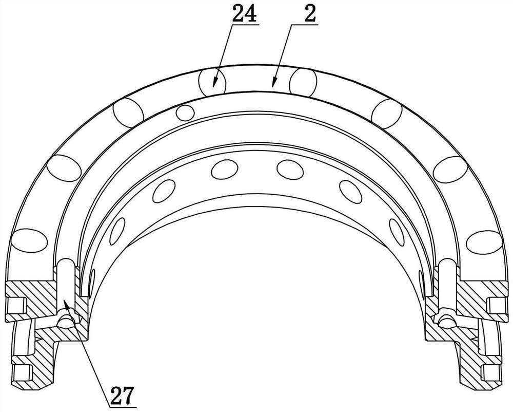
[0039] Such as Figure 1-11 As shown, a valve device with adjustable compression damping includes a valve seat 1, a valve sleeve 2, a valve body 3, a valve stem 4, a low-pressure valve pin 5, a high-pressure valve pin 6 and a slide valve assembly. The valve sleeve 2 is in the shape of a circular tube , the valve body 3 and the valve seat 1 are respectively located at the upper and lower ends of the valve sleeve 2, and the valve stem 4 for fastening the valve seat 1, the valve sleeve 2 and the valve body 3 passes through the valve body 3 from top to bottom and The thread fits on the valve seat 1;

[0040] The valve body 3 is provided with a low-pressure valve hole 17 and a high-pressure valve hole 18, and the outer wall of the valve body 3 is in sealing connection with the inner wall of the valve sleeve 2;

[0041] The upper part of the valve seat 1 is provided with a boss 7, which fits inside the valve sleeve 2 and has a first counterbore longitudinally. A second counterbore...


PUM


Abstract

The invention relates to a valve device with adjustable compression damping. The valve device comprises a valve seat, a valve sleeve, a valve body, a valve rod, a low-pressure valve pin, a high-pressure valve pin and a sliding valve assembly, wherein a plurality of flow guide holes are formed in the side wall of the valve sleeve in circumferential arrays, and the low-pressure valve pin and the high-pressure valve pin are both axially slidably arranged on the upper portion of the valve seat through springs correspondingly, drainage holes are formed in the upper portion of the low-pressure valvepin and the upper portion of the high-pressure valve pin correspondingly, and the sliding valve assembly is located in a sliding valve cavity. A shock absorber set for preventing vehicle roll comprises two shock absorbers, and each shock absorber comprises an oil storage cylinder, a working cylinder, an intermediate cylinder and the valve device. The invention aims to solve or at least relieve the problems that a traditional compression valve depends on an electric control system and a sensor, the product cost is high, and the system reliability is low, and provides the valve device with adjustable compression damping.

Description

technical field [0001] The invention relates to the technical field of shock absorbers, in particular to a valve device with adjustable compression damping. Background technique [0002] The compression valve system of twin-tube hydraulic shock absorbers commonly seen in the market is generally composed of a compensation valve and a compression valve. When the shock absorber is in the compression stroke, the oil can only flow out through the circulation valve and the compression valve to generate damping force. The structure, manufacturing and assembly process of the compression valve are relatively simple and become the mainstream of the current hydraulic shock absorber valve system, but its shortcomings are also obvious. The singleness of its oil passage also determines the compression of this structure after the shock absorber is assembled. The damping force value cannot be adjusted, so that the comfort and handling of the vehicle cannot be taken into account. [0003] A...

Claims


Application Information

Patent Timeline
Patent Type & Authority Applications(China)
IPC IPC(8): F16F15/023F16F15/067F16F9/32F16F9/34F16F9/54F16F9/50
CPCF16F9/3207F16F9/34F16F9/50F16F9/54F16F15/022F16F15/023F16F15/067
Inventor 王鹏刘向
Owner NANYANG XIJIAN AUTOMOBILE SHOCK ABSORBER
Learn More