
Visual bone grafting device

A technology of bone implantation and aggregate silo, applied in the field of medical devices, can solve the problems of prone to mistakes, patient injury, lack of visibility, etc., to achieve the effect of strong adaptability, improved effect, and avoidance of surgical injury

Active Publication Date: 2021-01-22
孙金堂
View PDF13 Cites 0 Cited by
  • Summary
  • Abstract
  • Description
  • Claims
  • Application Information

AI Technical Summary

Problems solved by technology

[0003] Among them, the problem with the original method is that it is necessary to repeatedly use instruments to remove the muscle and nerve tissue attached to the surface of the bone, which is likely to cause damage to the patient; while the improved method, although avoiding the above problems, does not have visibility, resulting in During the bone grafting process, it is easy to make mistakes when operating by feeling

Method used

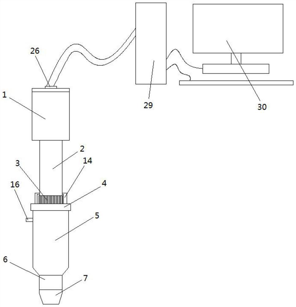

Image

  • Visual bone grafting device
  • Visual bone grafting device

Examples


Embodiment Construction

[0022] The following is a detailed description of the implementation of the present invention in a step-by-step manner. This description is only a preferred embodiment of the present invention, and is not used to limit the scope of protection of the present invention. Where the spirit and principles of the present invention Any amendments, equivalent replacements and improvements made within shall be included within the protection scope of the present invention.

[0023] In the description of the present invention, it should be noted that the orientations or positional relationships indicated by the terms "up", "down", "left", "right", "top", "bottom", "inner" and "outer" are based on those shown in the accompanying drawings. Orientation or positional relationship is only for describing the present invention and simplifying the description, rather than indicating or implying that the referred device or element must have a specific orientation, as well as a specific orientation ...


PUM


Abstract

The invention provides a visual bone grafting device, and relates to the technical field of medical instruments. The visual bone grafting device comprises a battery bin, a connecting pipe, an adjusting nut, a shell, a discharging pipe, a conical connector, a storage battery, a feeding pipe, an end cover, a sleeve, an aggregate bin, an operation bin, an annular discharging port, a built-in sleeve,a fixing block, a micro camera, a micro spotlight and a connecting pipe. During bone grafting, visual operation can be carried out, video information can be cleaned and displayed on a displayer, localdetails can be watched in an amplified mode, fine operation in the bone grafting process is facilitated, and human errors can be avoided to a great extent; the aggregate adding speed can be controlled through the adjusting nut, the bone grafting process is orderly and controllable, and the effect of a bone grafting operation can be remarkably improved; and through the opening effect of the conical connector, muscle tissue nerves at the bone wound surface of a patient can be prevented from being repeatedly stirred, and operation injuries are avoided; conical connectors of different types can be used for bone wound surfaces of different sizes, adaptability is high, and use is convenient.

Description

technical field [0001] The invention relates to the technical field of medical devices, in particular to a visual bone grafting device. Background technique [0002] There are generally two methods of bone grafting in orthopedics. One is a relatively primitive method, that is, the clinician uses tools to remove the muscle and nerve tissue attached to the surface of the bone, exposing the part that needs bone grafting, and then uses tweezers to remove the muscle and nerve tissue attached to the bone surface. The bone material is filled into the position where bone grafting is required; the other is an improved method, namely utilizing some bone grafting devices disclosed in existing patent documents for bone grafting. [0003] Among them, the problem with the original method is that it is necessary to repeatedly use instruments to remove the muscle and nerve tissue attached to the surface of the bone, which is likely to cause damage to the patient; while the improved method, ...

Claims


Application Information

Patent Timeline
Patent Type & Authority Applications(China)
IPC IPC(8): A61B17/88A61B90/00A61B17/02A61B90/30
CPCA61B17/8811A61B90/361A61B17/025A61B90/37A61B90/08A61B90/30A61B2017/564A61B2090/08021
Inventor 孙金堂王国荣俞秀茂
Owner 孙金堂
Learn More