Automatic hammer head-stick combining device
A technology of automatic combination and hammer stick, which is applied in metal processing, metal processing equipment, manufacturing tools, etc., can solve the problems of low combination efficiency, easy to be injured by tools, etc., and achieve the effect of easy collection
- Summary
- Abstract
- Description
- Claims
- Application Information
AI Technical Summary
Problems solved by technology
Method used
Image
Examples
Embodiment 1
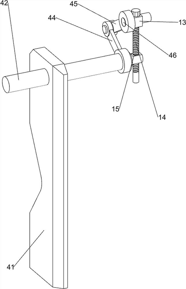
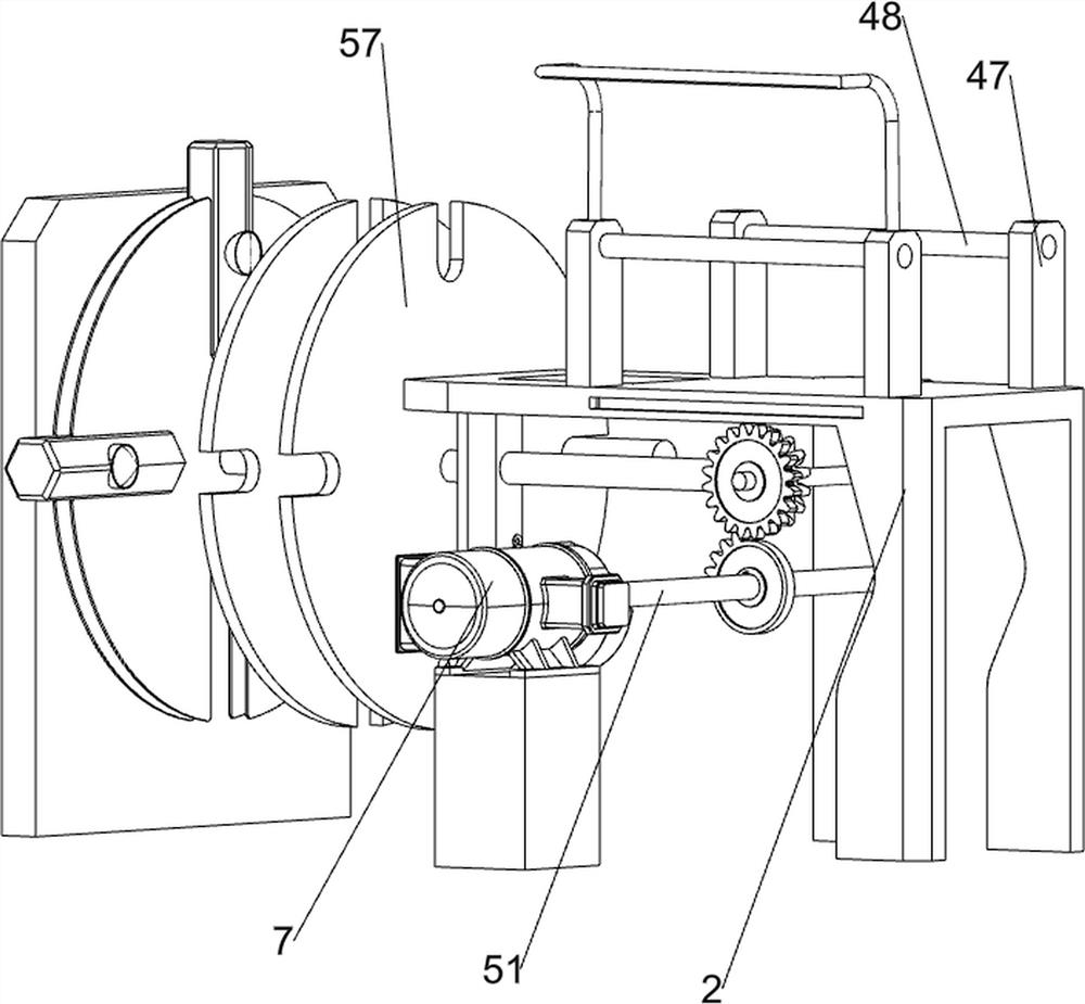
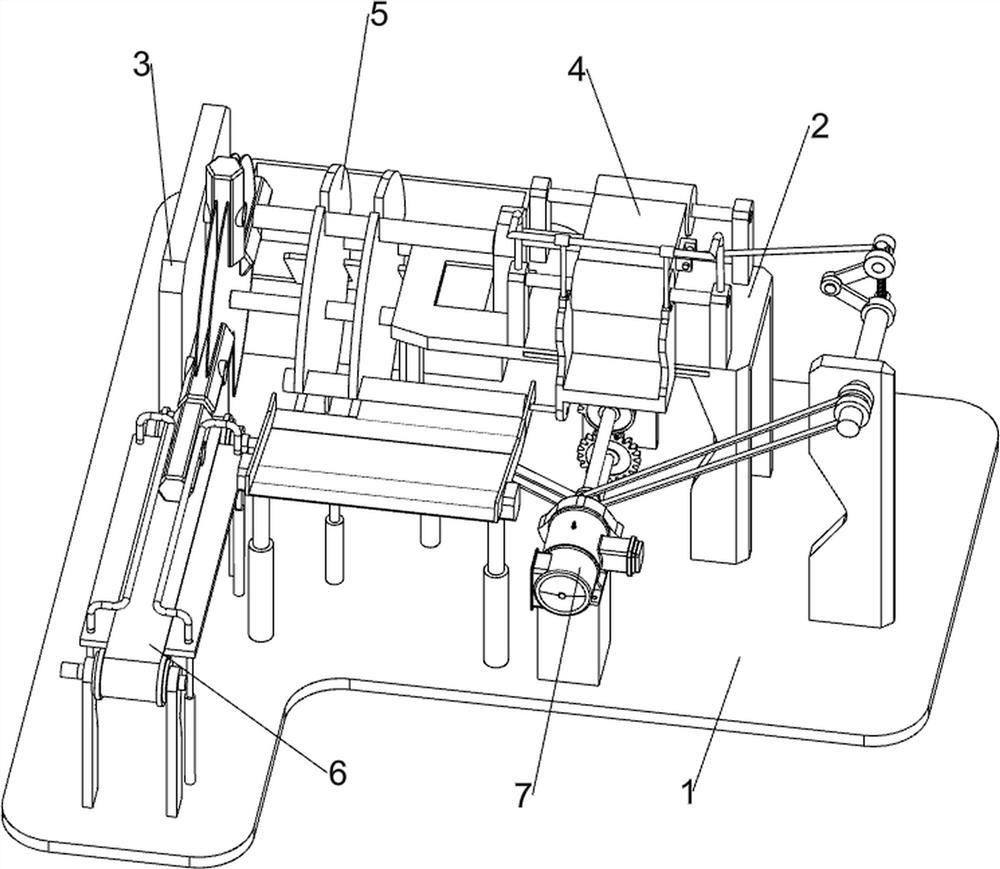
[0030] A hammer stick automatic combination device, such as Figure 1-8 As shown, it includes a bottom plate 1, a frame 2, a first support plate 3, a hammering mechanism 4, a clamping mechanism 5, a feeding mechanism 6 and a servo motor 7. A first support plate 3 is provided on the left side, a hammering mechanism 4 is provided on the frame 2, a clamping mechanism 5 is provided on the first support plate 3, a feeding mechanism 6 is provided on the top of the bottom plate 1, and a servo motor7.
[0031] When people need to use this device, first people place the hammer head on the feeding mechanism 6, and then the servo motor 7 can be started, and the servo motor 7 drives the hammering mechanism 4, the clamping mechanism 5 and the feeding mechanism 6 to operate, and the feeding mechanism 6 The operation further drives the tup to move backward to the clamping mechanism 5, and then the clamping mechanism 5 drives the tup to rotate upwards, so that the tup moves to the top of the...
Embodiment 2
[0039] On the basis of Example 1, such as Figure 6-9 As shown, it also includes a U-shaped connecting rod 8, a movable block 9, a push plate 10, a second support rod 11 and a first slide plate 12, and a U-shaped connecting rod is arranged between the tops of the two second supporting blocks 47 on the front side. 8. The U-shaped connecting rod 8 is provided with a movable block 9 in a sliding manner, and the movable block 9 is in contact with the slider 49. The lower part of the left side of the movable block 9 is provided with a push plate 10, and the front side of the bottom plate 1 is symmetrically provided with a second A first slide plate 12 is arranged between the top of the support bar 11 and the second support bar 11 , and the rear side of the bottom of the first slide plate 12 is connected with the bearing seat 63 .
[0040] First people put the stick on the first slide plate 12, when the chute on the first disc 57 rotates to the rear side of the first slide plate 12,...
PUM
 Abstract
Description
Claims
Application Information
 - R&D
- Intellectual Property
- Life Sciences
- Materials
- Tech Scout
- Unparalleled Data Quality
- Higher Quality Content
- 60% Fewer Hallucinations
Browse by: Latest US Patents, China's latest patents, Technical Efficacy Thesaurus, Application Domain, Technology Topic, Popular Technical Reports.
© 2025 PatSnap. All rights reserved.Legal|Privacy policy|Modern Slavery Act Transparency Statement|Sitemap|About US| Contact US: help@patsnap.com


