Supercharge Your Innovation With Domain-Expert AI Agents!

High-degree-of-freedom multi-angle adjusting type quick tool changing mechanism based on reliability design

A tool-changing mechanism and a degree of freedom technology, which is applied to large-scale fixed members, metal processing equipment, metal processing machinery parts, etc., can solve the problems of low tool switching efficiency, unsuitable machine tool sets, and cumbersome tool changing, so as to achieve the overall operation. Convenient and effective, avoid operation interference, and ensure the effect of operation accuracy

Active Publication Date: 2021-01-22
JILIN UNIV
View PDF9 Cites 2 Cited by
  • Summary
  • Abstract
  • Description
  • Claims
  • Application Information

AI Technical Summary

Problems solved by technology

However, it has certain operational defects, the overall tool change is more cumbersome, the efficiency of tool switching is low, and it is not suitable for conventional machine tool tool sets

Method used


Image

  • High-degree-of-freedom multi-angle adjusting type quick tool changing mechanism based on reliability design
  • High-degree-of-freedom multi-angle adjusting type quick tool changing mechanism based on reliability design
  • High-degree-of-freedom multi-angle adjusting type quick tool changing mechanism based on reliability design

Examples


Embodiment 1

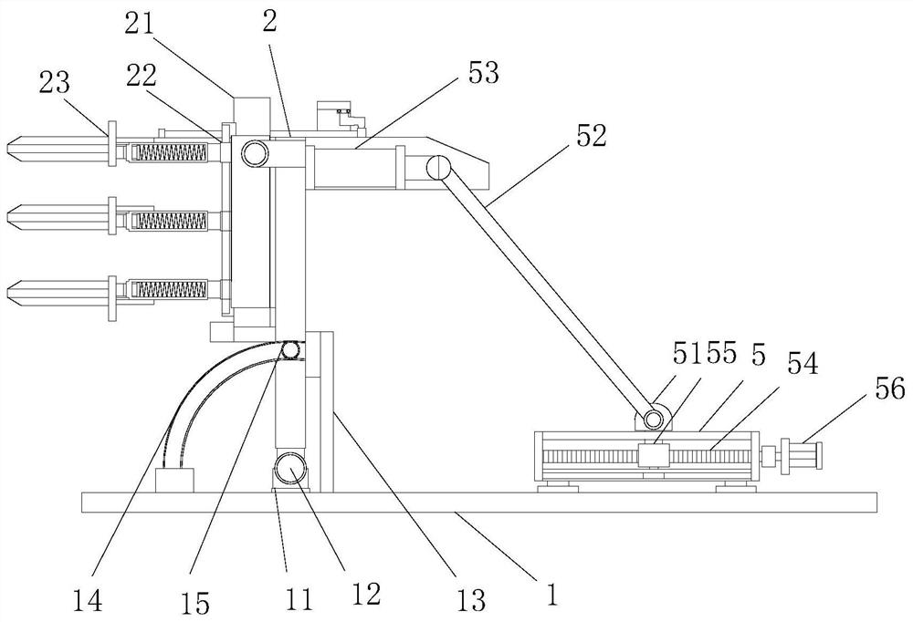
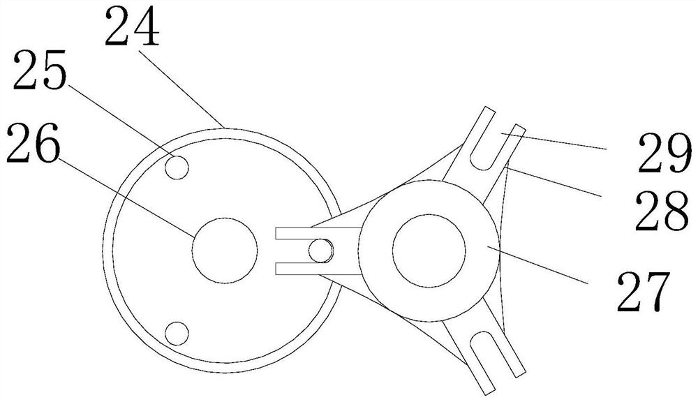
[0031] see figure 1 and figure 2 , a high-degree-of-freedom multi-angle adjustable quick tool change mechanism based on reliability design, including a base 1 and a tool holder 2, a tool change holder 21 is installed on the tool holder 2, and the main body of the tool change holder 21 It is a tool change carousel 24, and several positioning blocks 22 are installed at equal angles on the tool change carousel 24. Corresponding tool holders 23 are installed on the positioning blocks 22, and corresponding tool holders 23 are installed on the installation positions of the tool holders 23. Engaging cylinder 25, the engaging cylinder 25 is installed on the other side of the tool change turntable 24, the side of the tool change frame 21 is provided with a drive turntable 27, and the disk edge of the drive turntable 27 is equipped with several The outer edge block 28 is provided with a fitting notch 29 inside the outer edge block 28 , and the fitting notch 29 is matched with the enga...

Embodiment 2

[0036] see figure 1 , this embodiment is a further optimization of Embodiment 1. On the basis of it, a support seat 11 is installed on the base 1, and the tool holder 2 is installed on the support seat 11 through a rotating shaft 12. The support seat 11 Both sides are equipped with a positioning frame 13, the positioning frame 13 is equipped with a steering guide rail 14, the steering rail 14 is an arc structure and has a built-in arc notch, and the two side walls of the tool holder 2 are equipped with Slide bolt 15, said tool holder 2 is fitted and installed in the steering guide rail 14 through the slide bolt 15 of the side wall.

[0037] The base 1 is provided with an angle alternation frame 5, and the edge of the angle alternation frame 5 is movable through a chute to install a slider 51, and the slider 51 is externally equipped with a push rod 52, and the push rod 52 The front end of the rod is respectively fixed and installed with the two side plates of the tool holder ...


PUM


Abstract

The invention relates to the technical field of cutters, in particular to a high-degree-of-freedom multi-angle adjusting type quick tool changing mechanism based on reliability design, which comprisesa base and a tool frame. A supporting seat is arranged on the base; a tool changing frame is arranged on the tool frame; a main body of the tool changing frame is a tool changing rotary disc; a plurality of positioning blocks are arranged on the tool changing rotary disc at equal angles; corresponding tool bases are installed on the positioning blocks; corresponding clamping cylinders are installed at the installation positions of the tool bases; a driving rotary disc is arranged on the side edge of the tool changing frame; a plurality of outer edge blocks are installed at the disc edge position of the driving rotary disc at equal angles; embedded notches are formed in the outer edge blocks; each tool base comprises a tool and an installation base cylinder; a tool pushing frame is installed at the top of the tool frame; an upper edge limiting groove is formed in the tool pushing frame; a push rod is installed in the upper edge limiting groove; and an extrusion plate is installed at the front rod end of the push rod. According to the high-degree-of-freedom multi-angle adjusting type quick tool changing mechanism based on reliability design provided by the invention, the whole operation is conducted conveniently and simply, and tool changing treatment can be completed through two procedures of tool rotation and push rod transmission, so that the operation precision of the tool is guaranteed, operation is conducted conveniently and effectively, and high reliability is achieved.

Description

technical field [0001] The invention relates to the technical field of cutting tools, in particular to a high-degree-of-freedom multi-angle adjustable rapid tool change mechanism based on reliability design. Background technique [0002] When the tool has been used for a long time and needs to be polished or replaced, the entire slitting roller needs to be disassembled, and then the tool should be polished or replaced. The disassembly process is long, and the slitting roller needs to be calibrated after installation, which is a great waste Increased manpower and material resources, increased production costs. In the process of processing, tool drop is a common form of failure. During the movement of the tool change mechanism, the gravity of the tool due to its heavy mass, coupled with the centrifugal force of rotation, makes the tool of the tool change mechanism especially below the horizontal line. The downward part of the card slot is prone to the problem of knife drop. ...

Claims


Application Information

Patent Timeline
IPC IPC(8): B23Q3/157B23Q5/36B23Q1/01
CPCB23Q1/017B23Q3/157B23Q5/36
Inventor 陈传海池佳伟田海龙杨兆军金桐彤
Owner JILIN UNIV
Features
  • R&D
  • Intellectual Property
  • Life Sciences
  • Materials
  • Tech Scout
  • Unparalleled Data Quality
  • Higher Quality Content
  • 60% Fewer Hallucinations
Learn More